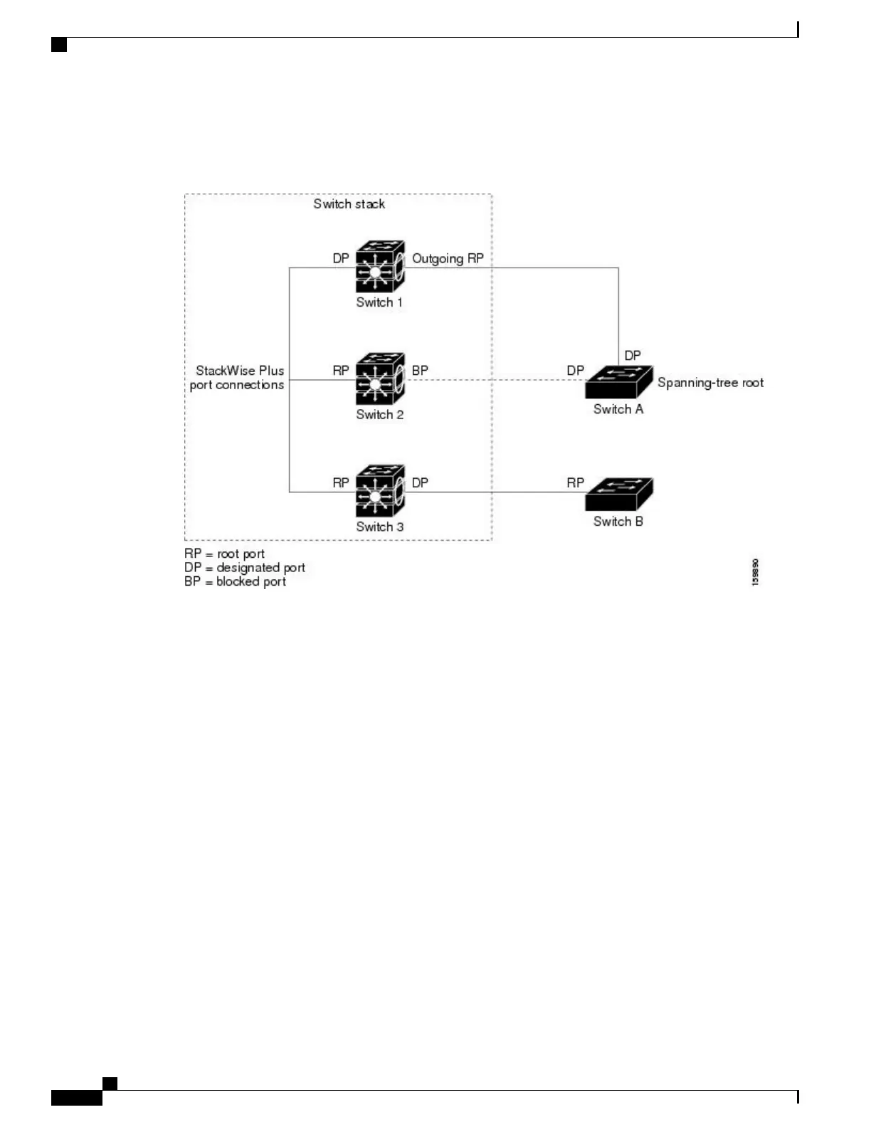
One stack member is elected as the stack root switch. The stack root switch contains the outgoing root port
(Switch 1).
Figure 8: Spanning-Tree Port States in a Switch Stack
All paths that are not needed to reach the root switch from anywhere in the switched network are placed in
the spanning-tree blocking mode.
Related Topics
Configuring the Root Switch , on page 227
Restrictions for STP, on page 211
Bridge ID, Device Priority, and Extended System ID
The IEEE 802.1D standard requires that each switch has an unique bridge identifier (bridge ID), which controls
the selection of the root switch. Because each VLAN is considered as a different logical bridge with PVST+
and Rapid PVST+, the same switch must have a different bridge ID for each configured VLAN. Each VLAN
on the switch has a unique 8-byte bridge ID. The 2 most-significant bytes are used for the switch priority, and
the remaining 6 bytes are derived from the switch MAC address.
The switch supports the IEEE 802.1t spanning-tree extensions, and some of the bits previously used for the
switch priority are now used as the VLAN identifier. The result is that fewer MAC addresses are reserved for
the switch, and a larger range of VLAN IDs can be supported, all while maintaining the uniqueness of the
bridge ID.
The 2 bytes previously used for the switch priority are reallocated into a 4-bit priority value and a 12-bit
extended system ID value equal to the VLAN ID.
Consolidated Platform Configuration Guide, Cisco IOS Release 15.2(4)E (Catalyst 2960-X Switches)
214
Information About Spanning Tree Protocol

 Loading...


