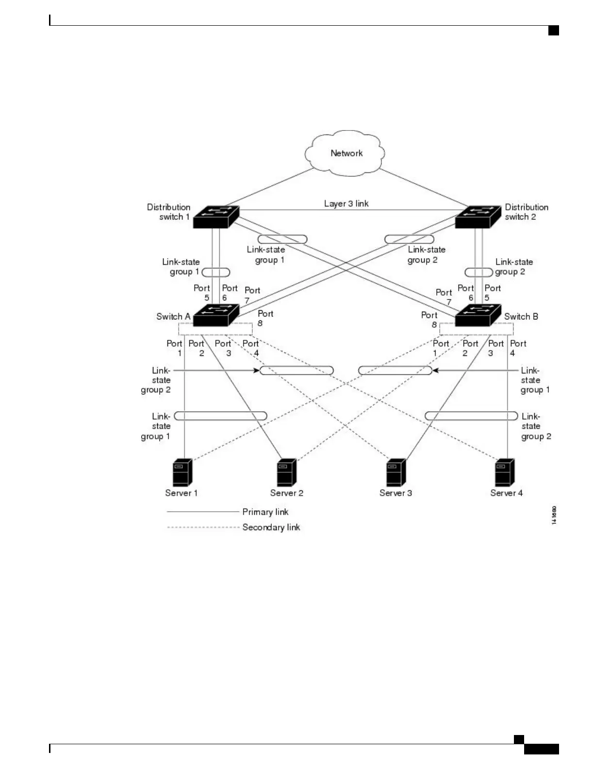
The configuration in this figure ensures that the network traffic flow is balanced.
Figure 38: Typical Link-State Tracking Configuration
•
For links to switches and other network devices
◦
Server 1 and server 2 use switch A for primary links and switch B for secondary links.
◦
Server 3 and server 4 use switch B for primary links and switch A for secondary links.
•
Link-state group 1 on switch A
◦
Switch A provides primary links to server 1 and server 2 through link-state group 1. Port 1 is
connected to server 1, and port 2 is connected to server 2. Port 1 and port 2 are the downstream
interfaces in link-state group 1.
Consolidated Platform Configuration Guide, Cisco IOS Release 15.2(4)E (Catalyst 2960-X Switches)
367
Understanding Link-State Tracking