Chapter 4: C4 CMTS General Installation Requirements
STANDARD Revision 1.0 C4® CMTS Release 8.3 User Guide
© 2016 ARRIS Enterprises LLC. All Rights Reserved. 114
How to Install the PCM
1. Be sure you are wearing an Electrostatic Discharge (ESD) strap when handling modules.
2. Ensure that no DC power cable is connected to the PCM.
3. Align the PCM on the rails in the rear of the chassis and slide firmly into place. From the rear, the PCM can be inserted
into either the left or right:
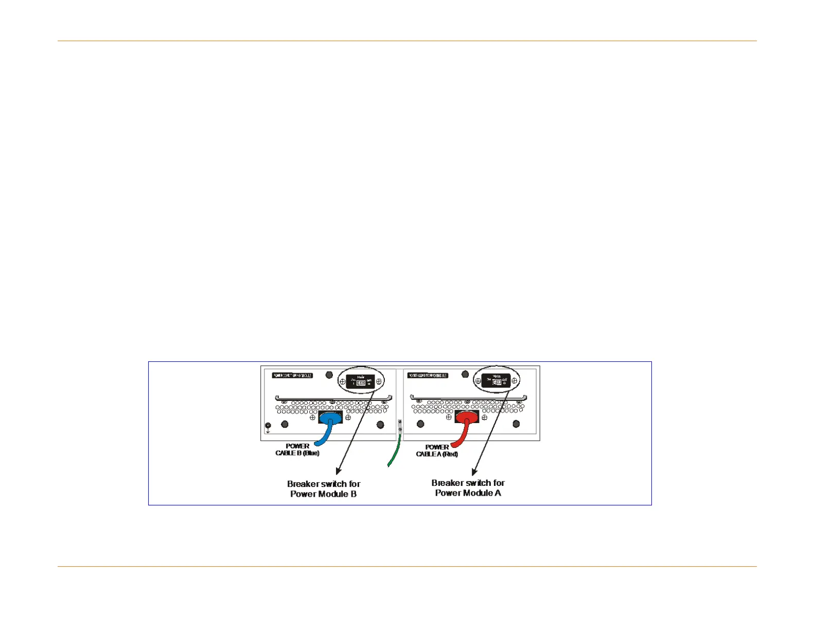
a. The PCM on the right side of the chassis is named PCM A. It corresponds to the Bus A power panel LEDs and control
switch located on the front of the chassis.
b. The PCM on the left side of the chassis is named PCM B. It corresponds to the Bus B power panel LEDs and control
switch located on the front of the chassis.
4. Hand tighten the three captive fasteners on each of the PCMs. If the captive fasteners are tightened using a tool, care
should be exercised not to over-tighten. The recommended torque for these fasteners is 5.0 ±0.5 inch-pounds.
Power Requirements
The C4 CMTS must be connected to a protected DC power source that meets the following current requirements:
Input voltage: A and B feed from –44V to -72V
Maximum required current for each feed: 65 amps
Figure 15: Cabling the PCM