Chapter 6: System Control Module (SCM)
STANDARD Revision 1.0 C4® CMTS Release 8.3 User Guide
© 2016 ARRIS Enterprises LLC. All Rights Reserved. 174
RJ-45–to–RJ-45 Serial Cable
a
RJ-45–to–DB-9
Terminal Adapter
a
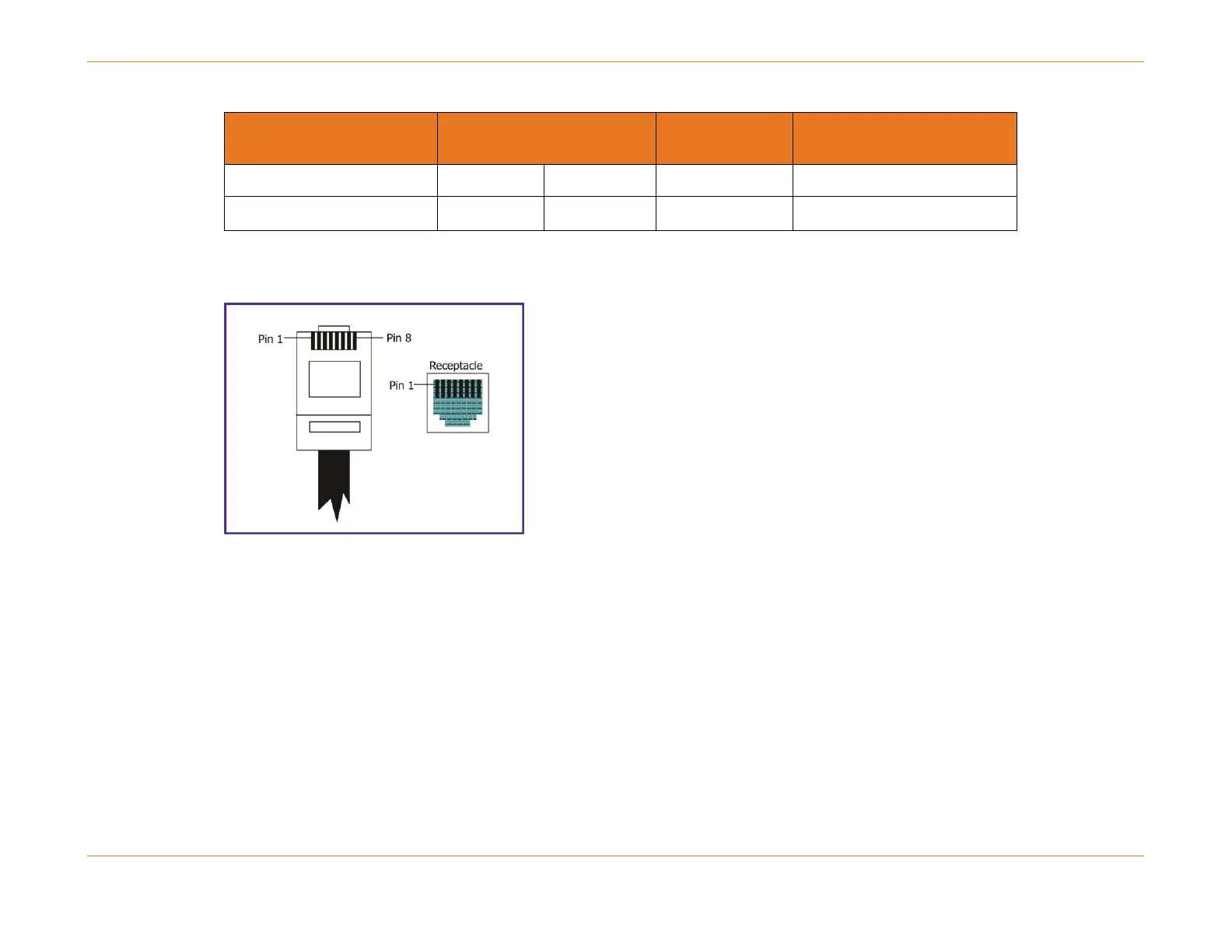
Pin 1 is on the left when the RJ-45 connector tab is facing down as shown in the following graphic:
Figure 44: View of Pin-out of Serial Cable
How to Cable the SCM
Perform the following steps to cable the operator console.
1. Locate the supplied 8-foot shielded Ethernet, 10 BaseT, RJ-45–to–RJ-45 Serial Cable and RJ-45–to–DB-9 female
connector.
2. Using the supplied Serial Cable, plug the RJ-45 end into the RS-232 connection on the front of the SCM.
3. Plug the other end of the RJ-45 cable into the RJ-45–to–DB-9 adapter.
4. Plug the adapter into your operator console.
5. When you are ready to begin configuring the CMTS, power on the chassis and boot the software using the procedures
in Replacing the C4 CMTS Chassis. Perform initial setup by entering CLI commands on the operator console.