Chapter 4: C4 CMTS General Installation Requirements
STANDARD Revision 1.0 C4® CMTS Release 8.3 User Guide
© 2016 ARRIS Enterprises LLC. All Rights Reserved. 121
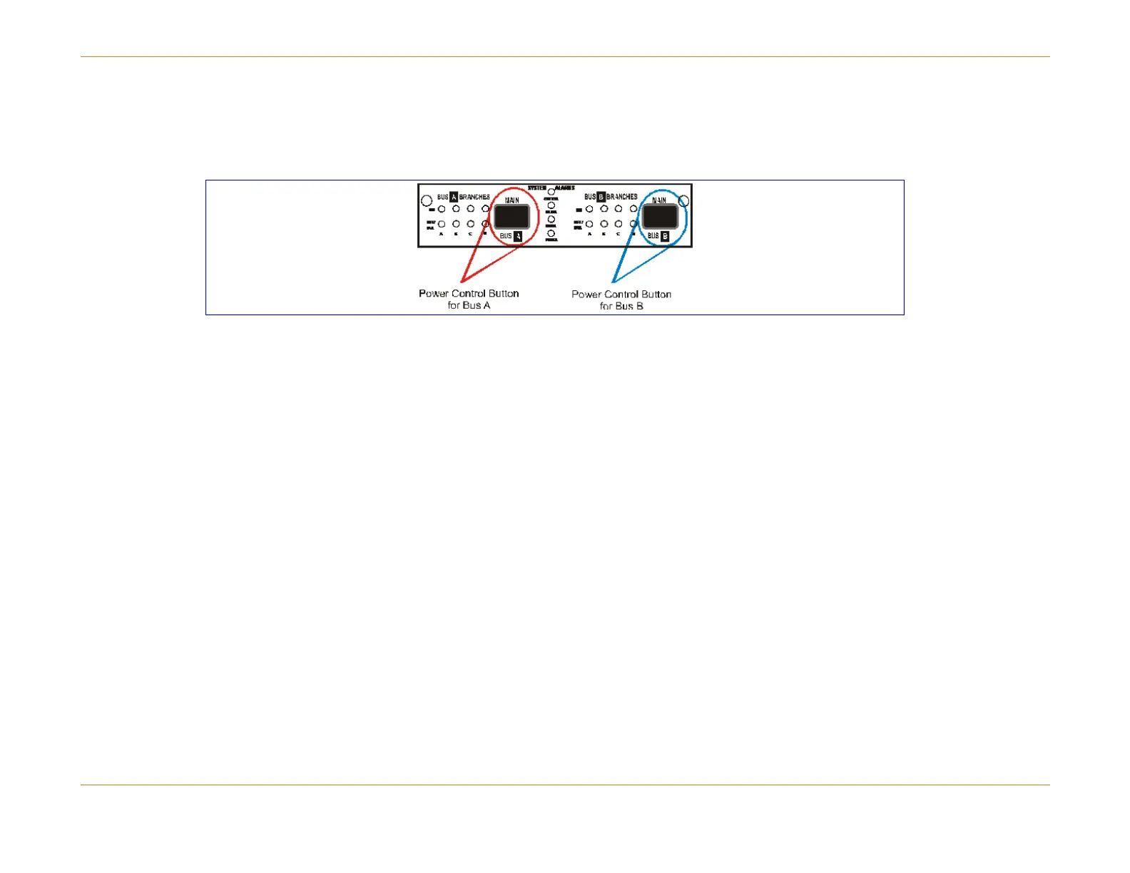
The entire feed for a side is turned on and off by pressing the power control button (the figure blow) on the power panel.
Each push of the button should be held approximately two seconds and will toggle the power from that feed (e.g., one
push turns it off, the next push turns it on). This is a delayed switch to prevent accidental activation.
Figure 20: Power Control Button
In the event of a power fault on a branch:
The electronic breaker for that branch detects the failure and removes power from that branch.
A system power alarm is generated.
The green power OK LED for that branch is turned off and the corresponding branch’s red power fault LED is turned on.
Module (Board-level) Fuses
The third level of protection is at the module level.
Each front module (CAM, RCM, or SCM) has two fuses that protect its internal circuitry.
One fuse is located on the circuit powered by the A bus; and the other on the circuit powered by the B bus.
These on-board module fuses are not field replaceable: if the fuse blows the module must be returned for repair.
Automatic Card Recovery for DC Voltage
Each front module of the C4 CMTS contains multiple DC-to-DC converters to supply the variety of voltages required by
module components. This capability functions independently for each front module and any voltage planes that fall out of
specification can trigger subtle and misleading faults.
In many cases, a voltage measurement that is only slightly out of specification in the High or Low Warning Level Threshold
will not affect the performance of a module and should be considered only as a warning to the operator to take action in