Chapter 6: System Control Module (SCM)
STANDARD Revision 1.0 C4® CMTS Release 8.3 User Guide
© 2016 ARRIS Enterprises LLC. All Rights Reserved. 169
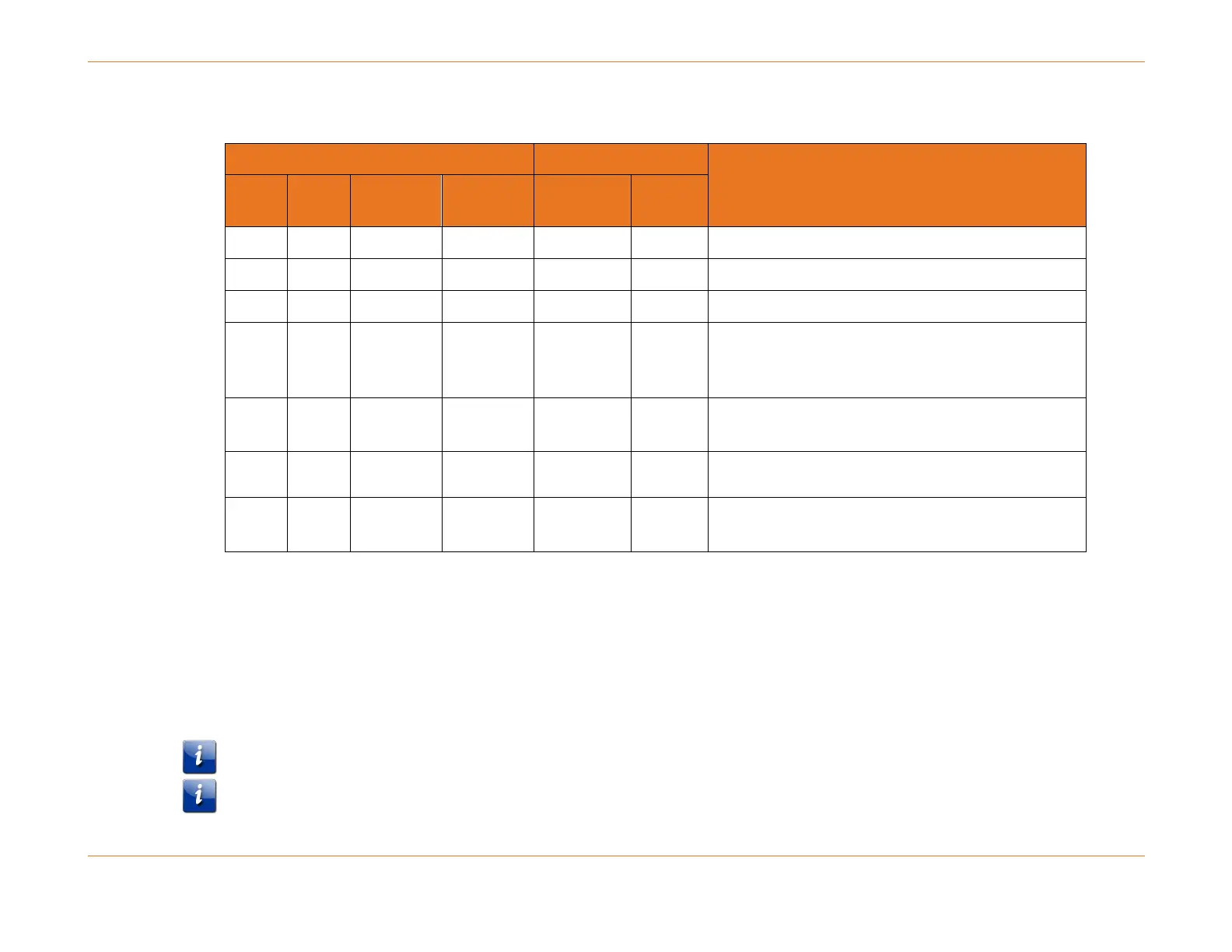
Table 16. LED Status Descriptions—System Control Module
Powered, in-service, but standby
Powered but out of service and not active
Powered, initializing, or running tests (not passing
traffic) and not active, or system-level fault
detected.
Powered, functional, and in service (normal
operational state)
Layer 2 connectivity established
Active traffic being passed
a
For the SCM 3, this LED is only available on the front of the module.
b
For the SCM 3, the LED is only available on the front of the module.
LED Test Button
The SCM provides an LED Test button in order to verify the functionality of all active LEDs in the chassis. Testing the LED
functionality on a chassis should be performed upon initialization, and then on a regularly scheduled basis in order to
ensure that all LEDs are functional.
The SCM LED Test Button is recessed. You will need something small and thin, such as a paper clip, to press it.
The following table lists the types of SCMs currently in the field. It includes the size of memory included and ordering codes
for each hardware type.