Chapter 9: Upstream Cable Access Modules (UCAMs)
STANDARD Revision 1.0 C4® CMTS Release 8.3 User Guide
© 2016 ARRIS Enterprises LLC. All Rights Reserved. 285
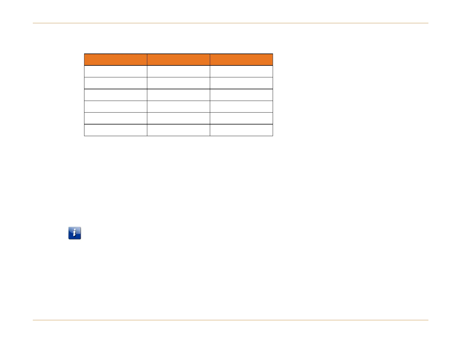
Table 46. US Receiver Power Level Group 5
Before Changing the Receive Power Level Settings of the 24U CAM
If there are multiple upstream channels on a single 24U CAM connector and the user is trying to change the receive power
level setting on one or more US channels and the new setting causes a change in the power level group (see Tables above),
then the user must complete the following steps:
1. Unassign (decouple) the corresponding connector (for all upstream channels that are on that connector).
2. Set the receive power level for all upstream channels on that connector.
3. Add the connector back for all upstream channels on that connector.
Note: The above procedure will not apply when the user changes receive power level setting on one or more upstream
channels on the same connector and the new setting does not cause a change in the amplifier attenuation settings. That is,
the new and old receive power level settings occur within the same amplifier attenuation setting (per the tables listed in
the see "24U CAM Upstream Power Level Groups (page 282)).
The following is an example of setting the upstream channels receive power level (attenuation) that will cause a change in
the amplifier attenuation settings. Upstream channels 3/0 and 3/1 have the following initial power and channel width
settings (3.2 and 6.4 MHz and power level 0):
configure interface cable-upstream 3/0 shutdown
configure interface cable-upstream 3/1 shutdown
configure interface cable-upstream 3/0 cable connector no