Chapter 3: C4/C4c CMTS Specifications
STANDARD Revision 1.0 C4® CMTS Release 8.3 User Guide
© 2016 ARRIS Enterprises LLC. All Rights Reserved. 77
physical connectors for terminating cables from the subscriber. Between the front and back slots is the midplane of the
chassis.
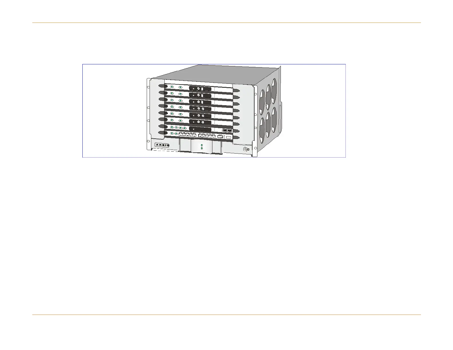
Figure 3: The C4c CMTS (front view)
Slot Numbering Scheme
The eight slots from top to bottom are numbered and populated as follows:
Slot 15 16D or XD CAM
Slot 14 12U or 16D or XD CAM
Slot 13 12U or 16D or XD CAM
Slot 12 12U or 16D or XD CAM
Slot 11 12U or 16D or XD CAM
Slot 10 12U CAM
Slot 19 SCM
Slot 17 RCM
The slot numbering scheme makes the C4c CMTS compatible with C4 CMTS software. Without this numbering scheme the
software would return provisioning errors for cards used in the wrong slots.
The CAMs, RCM, SCM, power modules, and Fan Tray Module plus filter are hot-swappable and field-replaceable units.