Chapter 3: C4/C4c CMTS Specifications
STANDARD Revision 1.0 C4® CMTS Release 8.3 User Guide
© 2016 ARRIS Enterprises LLC. All Rights Reserved. 75
Network Diagram
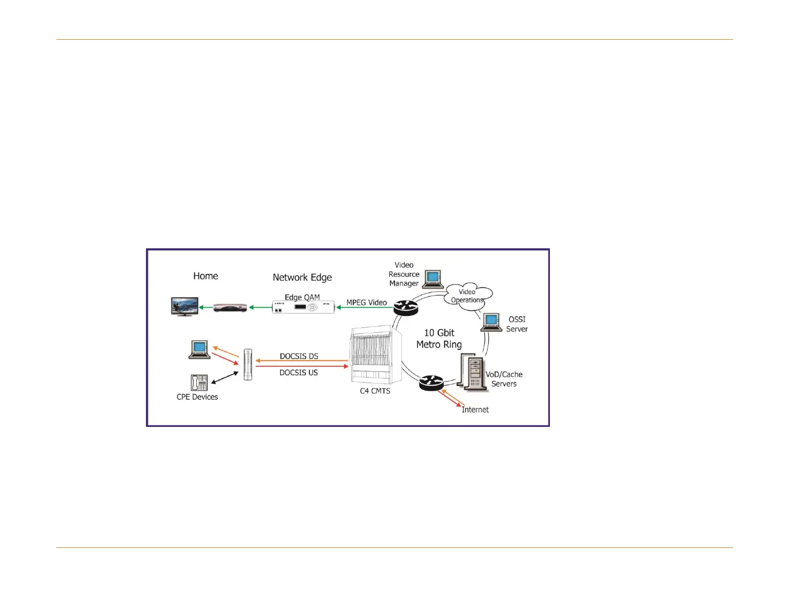
A cable network system consists of cable modems (CMs) at subscriber premises, a C4/C4c CMTS at the cable plant
operations area, a data-over-cable management software suite integrated with the operator's other management systems,
and the Hybrid Fiber Coaxial (HFC) cabling that connects it all.
DOCSIS defines the standard for communication among these elements. The C4/C4c CMTS provides data switching
functions as well as the radio frequency (RF) interface to and from the cable plant. It also provides ethernet interfaces to
the Internet Service Provider(s).
The data-over-cable management system provides both the end-to-end network management solution and the support for
subscriber provisioning. The figure below shows a typical cable network architecture.
Figure 1: Typical Cable Network Architecture