Chapter 21: Integrated Upstream Agility
STANDARD Revision 1.0 C4® CMTS Release 8.3 User Guide
© 2016 ARRIS Enterprises LLC. All Rights Reserved. 665
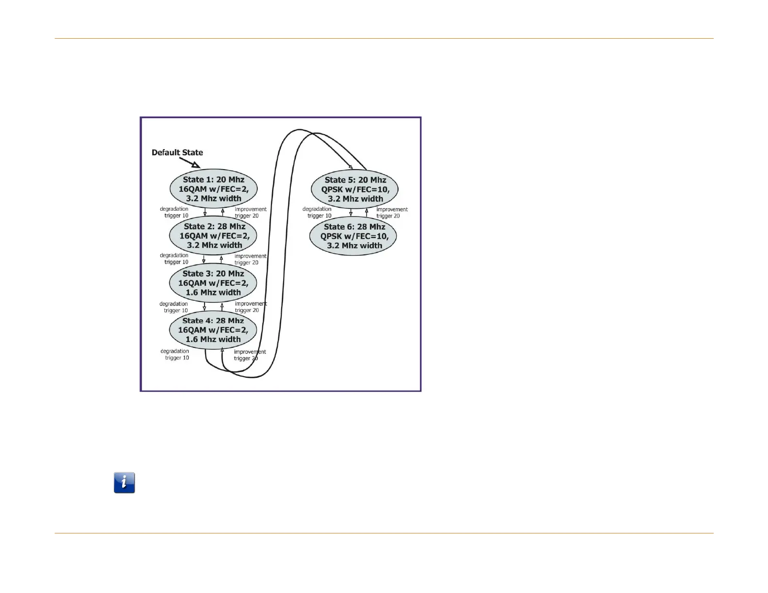
There are many ways to chain these states together in a meaningful fashion to create an Upstream Agility state machine.
For example, the chain of states shown below might be one way for the system operator to achieve the desired channel
performance.
Figure 86: State Diagram of a State Machine (Example)
The following CLI commands will create the state machine shown in the figure above:
configure cable modulation-profile 1000 tdma qpsk
configure cable modulation-profile 1100 tdma qam-16
Note: Some of the commands used to modify FEC are not shown.
configure cable spectrum-group trigger 10 degradation fec_err 4000 ufec_err 3000 SNR 220
configure cable spectrum-group trigger 20 improvement fec_err 2000 ufec_err 1000 SNR 250