Chapter 9: Upstream Cable Access Modules (UCAMs)
STANDARD Revision 1.0 C4® CMTS Release 8.3 User Guide
© 2016 ARRIS Enterprises LLC. All Rights Reserved. 280
Downloading data from SCM, initializing or running diagnostics.
Shuffle Network
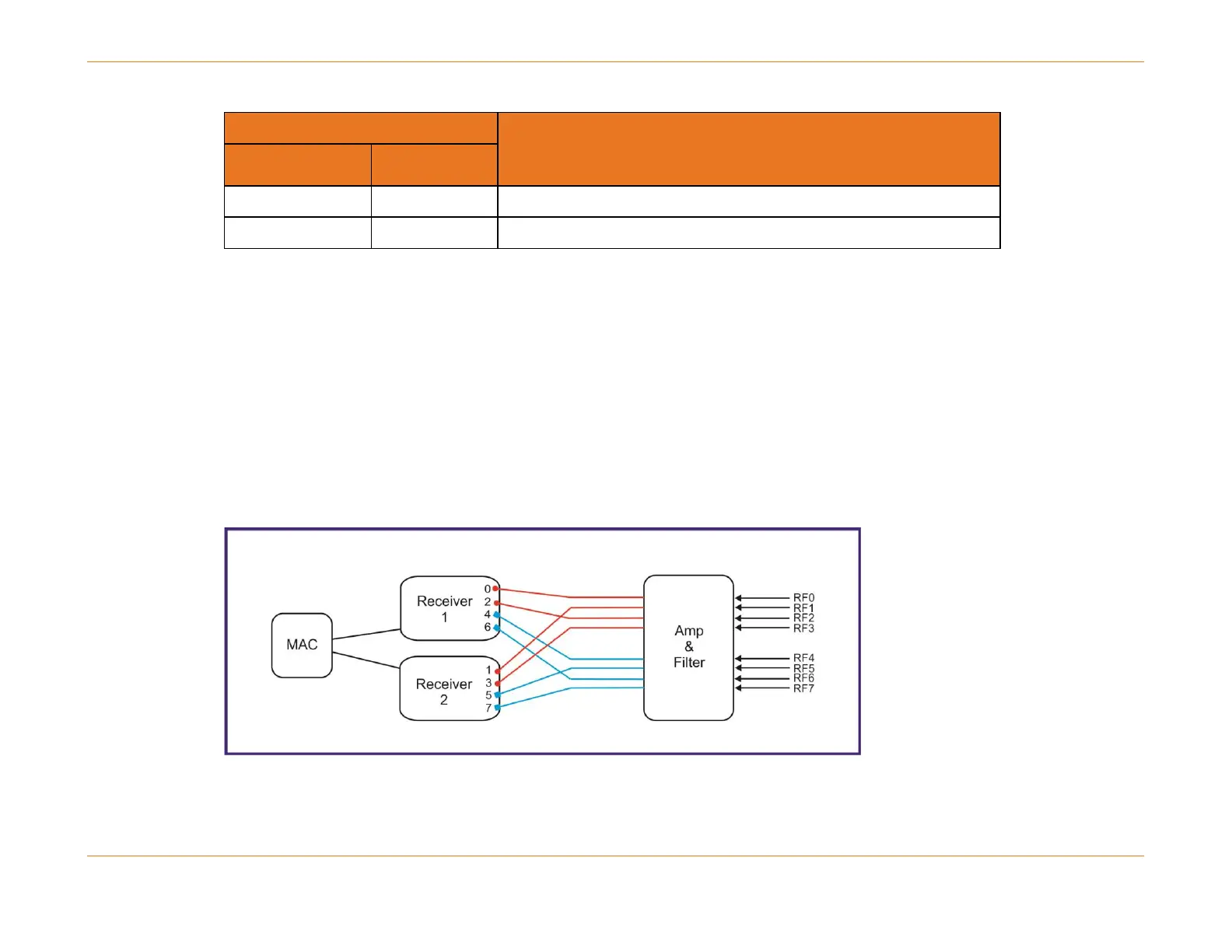
The Shuffle network spreads upstream channels across multiple PHY chips as the MSO populates the RF connectors in
order from top to bottom. When fewer than eight F-connectors are wired (e.g. connectors 0 through 3), the shuffle
network will enable the operator to access all 24 upstreams.
The 24U CAM will support 24 upstream channels using eight connectors through the current 12U PIC.
With the Shuffle network, connectors 0, 2, 4, 6 are connected to the first chip (upstream receivers 0 through 11) and
connectors 1, 3, 5, 7 will be connected to the second chip (upstream receivers 12 through 23) as shown in the figure below.
Figure 66: Illustration of the Shuffle Network