Chapter 4: C4 CMTS General Installation Requirements
STANDARD Revision 1.0 C4® CMTS Release 8.3 User Guide
© 2016 ARRIS Enterprises LLC. All Rights Reserved. 119
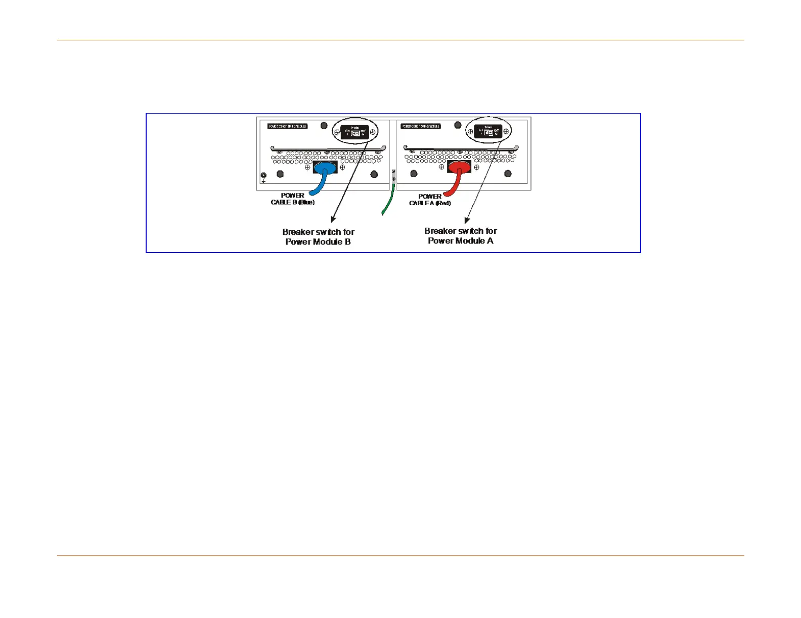
They also serve as the master power switch for the unit. The breakers protect the cables within the C4 CMTS which carry
high current and the power connectors located at the rear of the unit.
Figure 18: C4 CMTS Power Feeds (chassis rear)
Internal Branch Protection
Each A and B power feed is further divided into four internal chassis distribution branches, A through D. Each of these
branches is protected by both an electronic circuit breaker and a 20-amp fuse located in the PCM. These fuses constitute
the second level of protection. They are not field replaceable, nor can they be reset.