Chapter 5: C4c CMTS Installation Requirements
STANDARD Revision 1.0 C4® CMTS Release 8.3 User Guide
© 2016 ARRIS Enterprises LLC. All Rights Reserved. 152
The source can be an external battery plant or independent AC or DC power supply. The C4c CMTS chassis can have a DC,
AC, AC/DC, DC/DC, or AC/AC Power Module configuration.
The PM contains the power input connector, main breaker, and all active circuitry for power distribution of a power bus.
The Power Module:
Soft starts the chassis on power up
Filters noise and power disturbances from the power feeds
Monitors the power draw of the chassis and shuts down a branch circuit in the event of a power fault
Note: Review the total current consumption of all equipment on the same line before supplying power to the C4c CMTS.
Avoid sharing a power source that requires large currents.
Each PM is removable and can be replaced without interrupting power to the C4c CMTS in a duplex power configuration.
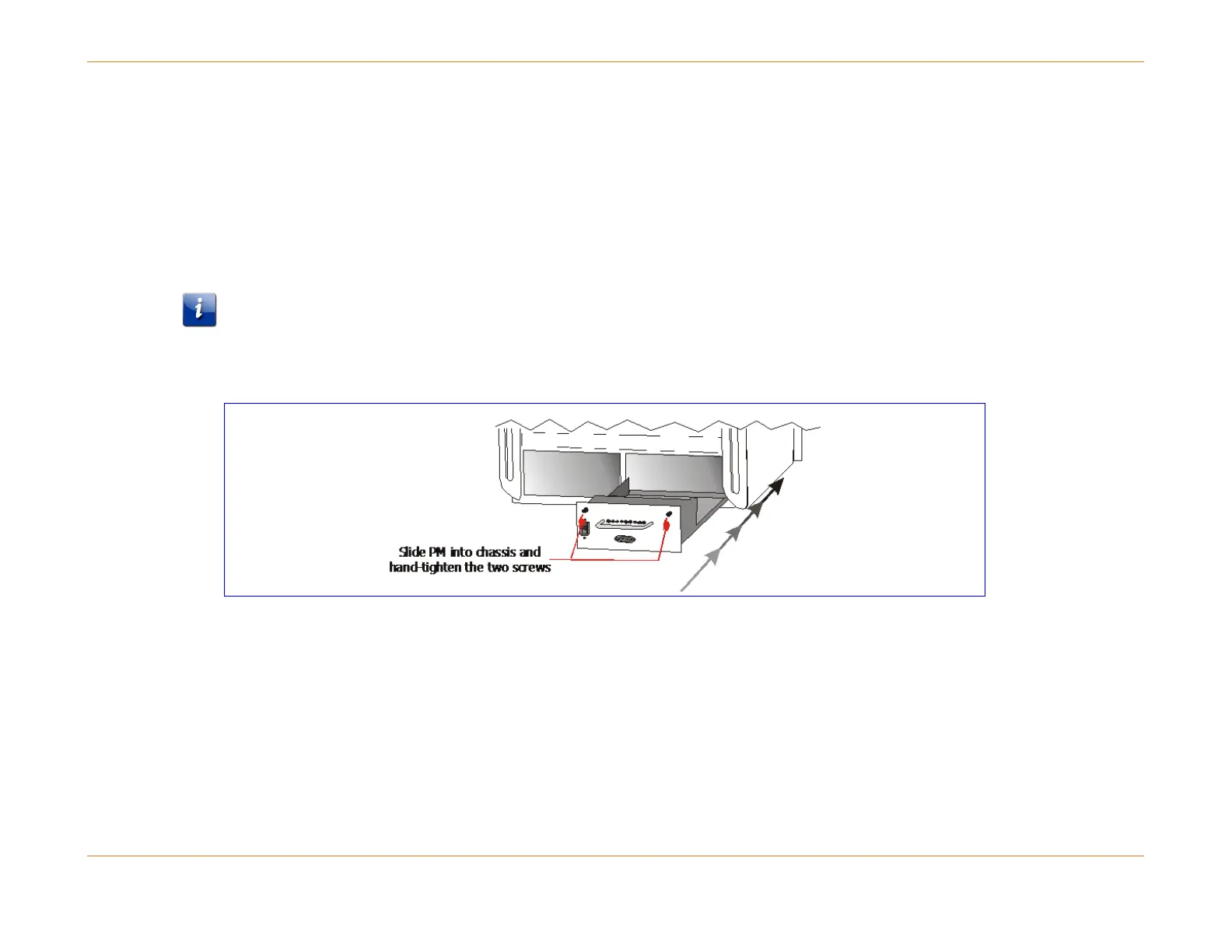
Figure 33: Installing the PM
How to Install the PMs
Refer to the above figure and follow these steps to install the PMs:
1. Be sure you are wearing an Electrostatic Discharge (ESD) strap when handling modules.
2. Ensure that no power cables are attached to the PMs.
3. Align the PM on the rails in the rear of the chassis and slide firmly into place. From the rear, the PM can be inserted
into either the left or right: