RM0046 Deserial Serial Peripheral Interface (DSPI)
Doc ID 16912 Rev 5 461/936
The DCONF field in the DSPIx_MCR register determines the DSPI configuration. Refer to
Table 206 for the DSPI configuration values.
The DSPIx_CTAR0–DSPIx_CTAR7 registers hold clock and transfer attributes.The SPI
configuration can select which CTAR to use on a frame by frame basis by setting the CTAS
field in the DSPIx_PUSHR.
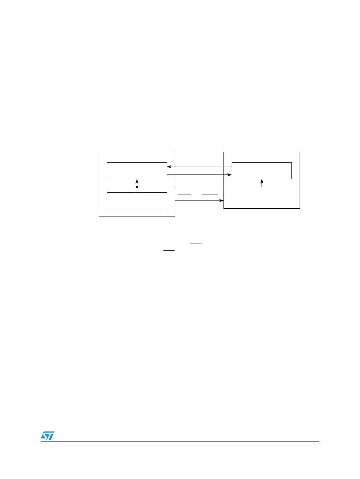
The 16-bit shift register in the master and the 16-bit shift register in the slave are linked by
the SOUT_x and SIN_x signals to form a distributed 32-bit register. When a data transfer
operation is performed, data is serially shifted a pre-determined number of bit positions.
Because the registers are linked, data is exchanged between the master and the slave; the
data that was in the master’s shift register is now in the shift register of the slave, and vice
versa. At the end of a transfer, the TCF bit in the DSPIx_SR is set to indicate a completed
transfer. Figure 216 illustrates how master and slave data is exchanged.
Figure 216. SPI serial protocol overview
Each DSPI has four peripheral chip select (CS
x) signals that select the slaves with which to
communicate (DSPI_0 has eight CS
x signals.)
Transfer protocols and timing properties are shared by the three DSPI configurations; these
properties are described independently of the configuration in Section 20.8.5, “Transfer
formats. The transfer rate and delay settings are described in Section 20.8.4, “DSPI baud
rate and clock delay generation.
Refer to Section 20.8.8, “Power saving features for information on the power-saving features
of the DSPI.
20.8.1 Modes of operation
The DSPI modules have four available distinct modes:
● Master mode
● Slave mode
● Module disable mode
● Debug mode
Master, slave, and module disable modes are module-specific modes while debug mode is a
device-specific mode. All four modes are implemented on this device.
The module-specific modes are determined by bits in the DSPIx_MCR. Debug mode is a
mode that the entire device can enter in parallel with the DSPI being configured in one of its
module-specific modes.
DSPI Master
Shift register
Baud rate generator
DSPI Slave
Shift register
SOUT_x
SIN_x
SOUT_x SIN_x
SCK_x SCK_x
CS_x CS0_x