RM0046 FlexPWM
Doc ID 16912 Rev 5 677/936
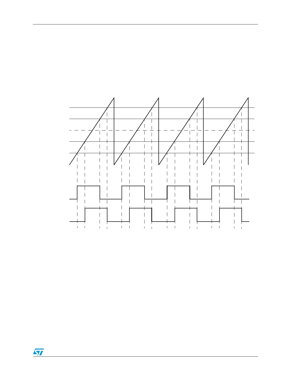
are applied to the turn on and turn off edges of different PWM signal, the signals will be
phase shifted with respect to each other, as illustrated in Figure 363. This results in certain
advantages when applied to a power stage. For example, when operating a multi-phase
inverter at a low modulation index, all of the PWM switching edges from the different phases
occur at nearly the same time. This can be troublesome from a noise standpoint, especially
if ADC readings of the inverter must be scheduled near those times. Phase shifting the
PWM signals can open up timing windows between the switching edges to allow a signal to
be sampled by the ADC. However, phase shifting does not affect the duty cycle so average
load voltage is not affected.
Figure 363. Phase-shifted outputs example
An additional benefit of phase-shifted PWMs can be seen in Figure 364. In this case, an H-
bridge circuit is driven by four PWM signals to control the voltage waveform on the primary
of a transformer. Both left and right side PWMs are configured to always generate a square
wave with 50% duty cycle. This works for the H-bridge since no narrow pulse widths are
generated, reducing the high-frequency switching requirements of the transistors. Notice
that the square wave on the right side of the H-Bridge is phase-shifted compared to the left
side of the H-Bridge. As a result, the transformer primary sees the bottom waveform across
its terminals. The RMS value of this waveform is directly controlled by the amount of phase
shift of the square waves. Regardless of the phase shift, no DC component appears in the
load voltage as long as the duty cycle of each square wave remains at 50%, making this
technique ideally suited for transformer loads. As a result, this topology is frequently used in
industrial welders to adjust the amount of energy delivered to the weld arc.
VAL1 (0x0100)
VAL5
VAL3
VAL0 (0x0000)
VAL4
VAL2
INIT (0xFF00)
PWMA
PWMB