RM0046 FlexPWM
Doc ID 16912 Rev 5 679/936
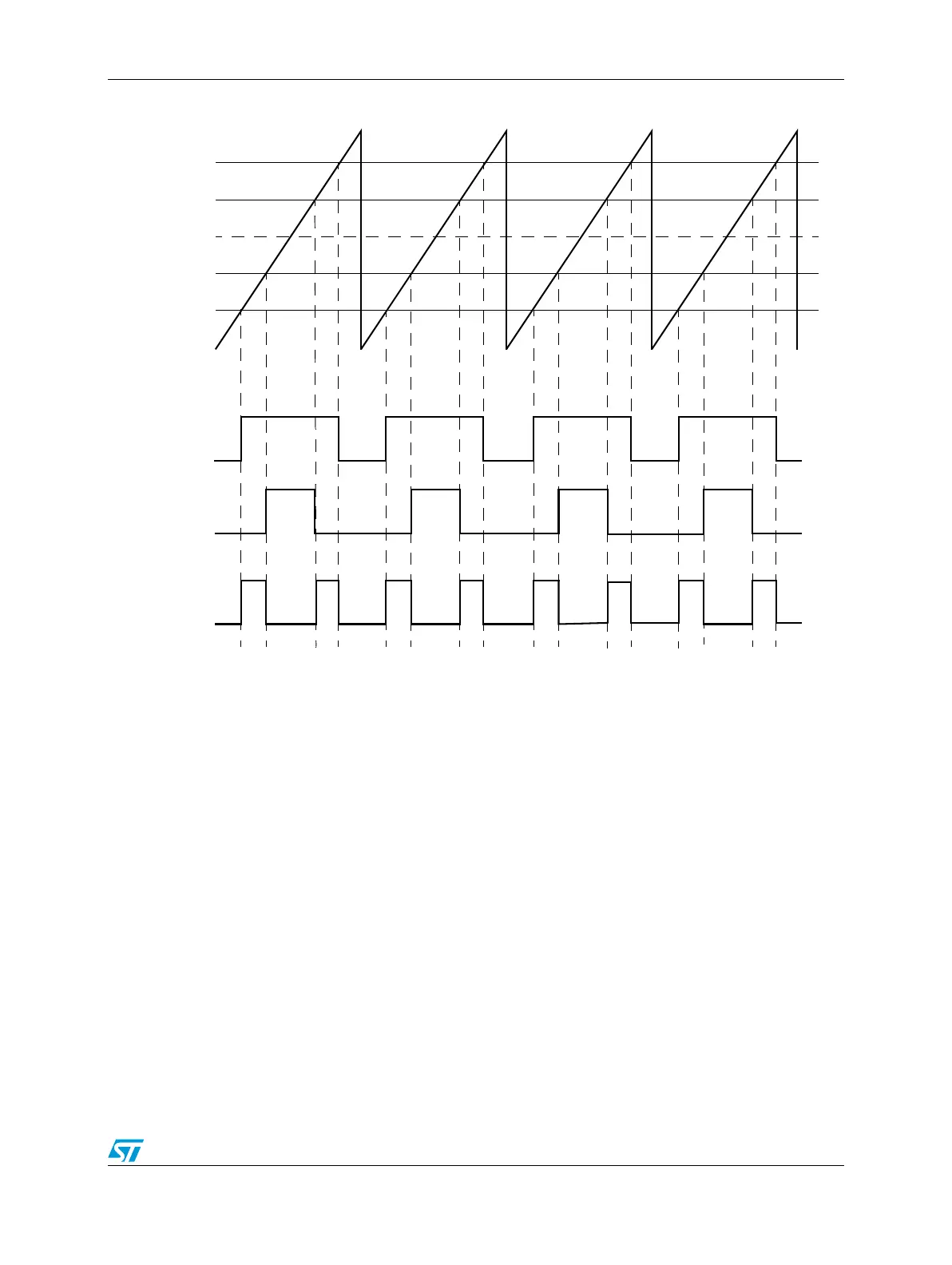
Figure 365. Double switching output example
25.7.5 ADC triggering
In cases where the timing of the ADC triggering is critical, it must be scheduled as a
hardware event instead of software activated. With this PWM module, multiple ADC triggers
can be generated in hardware per PWM cycle without the requirement of another timer
module. Figure 366 shows how this is accomplished. When specifying complimentary mode
of operation, only two edge comparators are required to generate the output PWM signals
for a given submodule. This means that the other comparators are free to perform other
functions. In this example, the software does not need to respond quickly after the first
conversion to set up other conversions that must occur in the same PWM cycle.
VAL1 (0x0100)
VAL3
VAL5
VAL0 (0x0000)
VAL4
VAL2
INIT (0xFF00)
PWMA
PWMB
DBLPWM