Clock Description RM0046
108/936 Doc ID 16912 Rev 5
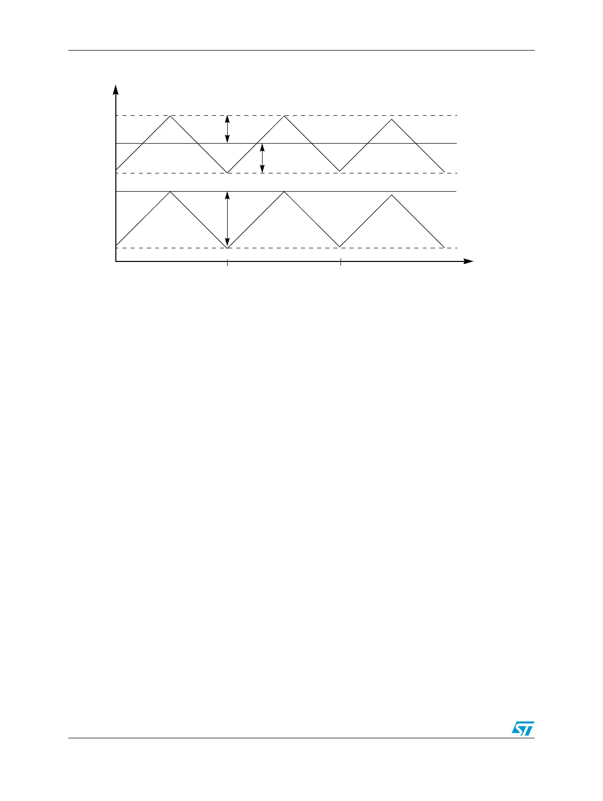
Figure 18. Frequency modulation depth spreads
Powerdown mode
To reduce consumption, the FMPLL can be switched off when not required by programming
the registers ME_x_MC on the ME module.
4.8.7 Recommendations
To avoid any unpredictable behavior of the PLL clock, it is recommended to follow these
guidelines:
● The PLL VCO frequency should reside in the range 256 MHz to 512 MHz. Care is
required when programming the multiplication and division factors to respect this
requirement.
● The user must change the multiplication, division factors only when the PLL output
clock is not selected as system clock. MOD_PERIOD, INC_STEP, SPREAD_SEL bits
should be modified before activating the FM modulated mode. Then strobe has to be
generated to enable the new settings. If STRB_BYP is set to ‘1’ then MOD_PERIOD,
INC_STEP and SPREAD_SEL can be modified only when PLL is in power down mode.
● Use progressive clock switching.
4.9 Clock Monitor Unit (CMU)
4.9.1 Overview
The Clock Monitor Unit (CMU) serves three purposes:
● PLL clock monitoring: detects if PLL leaves an upper or lower frequency boundary
● XOSC clock monitoring: monitor the XOSC clock, which must be greater than the
IRCOSC clock divided by a division factor given by CMU_CSR[RCDIV]
● Frequency meter: measure the frequency of the IRCOSC clock versus the reference
XOSC clock frequency
Time
Frequency
F0
F0
Center Spread
Down Spread
md
md
2× md
T
mod
2T
mod