RM0046 System Status and Configuration Module (SSCM)
Doc ID 16912 Rev 5 241/936
10.1.3 Modes of operation
The SSCM operates identically in all system modes.
10.2 Memory map and register description
This section provides a detailed description of all memory-mapped registers in the SSCM.
10.2.1 Memory map
Table 7 7 shows the memory map for the SSCM. Note that all addresses are offsets; the
absolute address may be calculated by adding the specified offset to the base address of
the SSCM.
All registers are accessible via 8, 16 or 32-bit accesses. However, 16-bit accesses must be
aligned to 16-bit boundaries, and 32-bit accesses must be aligned to 32-bit boundaries. As
an example, the MEMCONFIG register is accessible by a 16-bit read/write to address Base
+ 0x0002, but performing a 16-bit access to Base + 0x0003 is illegal.
10.2.2 Register description
Each description includes a standard register diagram. Details of register bit and field
function follow the register diagrams, in bit order. The numbering convention of the registers
is MSB = 0, however the numbering of the internal fields is LSB = 0, for example, register
SSCM_STATUS[8] = BMODE[2].
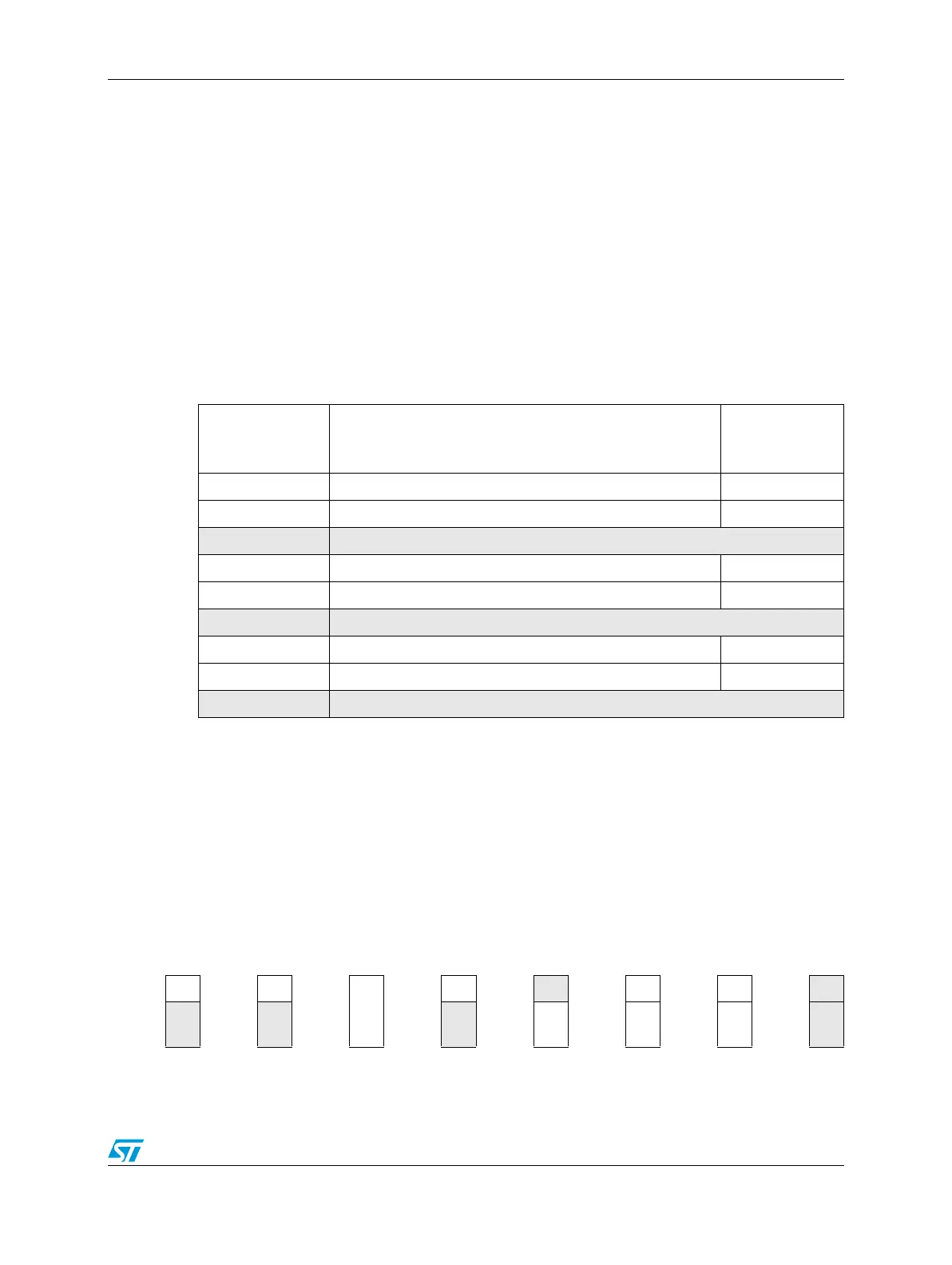
Figure 89. Key to register fields
Table 77. SSCM memory map
Offset from
SSCM_BASE
(0xC3FD_8000)
Register Location
0x0000 STATUS—System Status register on page 10-242
0x0002 MEMCONFIG—System Memory Configuration register on page 10-243
0x0004 Reserved (Reads/Writes have no effect)
0x0006 ERROR—Error Configuration register on page 10-244
0x0008 DEBUGPORT—Debug Status Port register on page 10-245
0x000A Reserved (Reads/Writes have no effect)
0x000C
PWCMPH—Password Comparison High Word register
on page 10-246
0x0010
PWCMPL—Password Comparison Low Word register
on page 10-246
0x0014–0x3FFF Reserved
Always
reads 1
1
Always
reads 0
0
R/W
bit
BIT
Read-
only bit
BIT
Write-
only bit
Write 1
to clear
BIT
Self-
clear
bit
0
N/A
BIT
w1
c
BIT