FlexPWM RM0046
680/936 Doc ID 16912 Rev 5
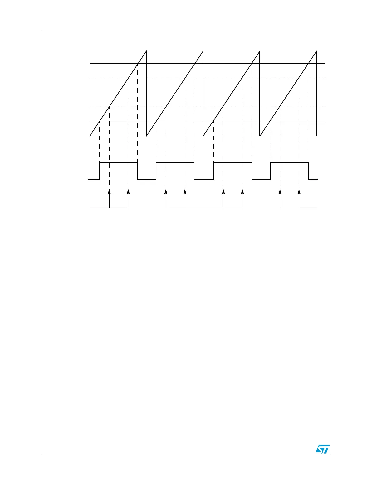
Figure 366. Multiple output trigger generation in hardware
Since each submodule has its own timer, it is possible for each submodule to run at a
different frequency. One of the options possible with this PWM module is to have one or
more submodules running at a lower frequency, but still synchronized to the timer in
submodule 0. Figure 367 shows how this feature can be used to schedule ADC triggers over
multiple PWM cycles. A suggested use for this configuration would be to use the lower
frequency submodule to control the sampling frequency of the software control algorithm
where multiple ADC triggers can now be scheduled over the entire sampling period. In
Figure 367, ALL submodule comparators are shown being used for ADC trigger generation.
VAL1 (0x0100)
VAL3
VAL5
VAL4
VAL2
INIT (0xFF00)
PWM
Output Triggers