RM0046 Deserial Serial Peripheral Interface (DSPI)
Doc ID 16912 Rev 5 477/936
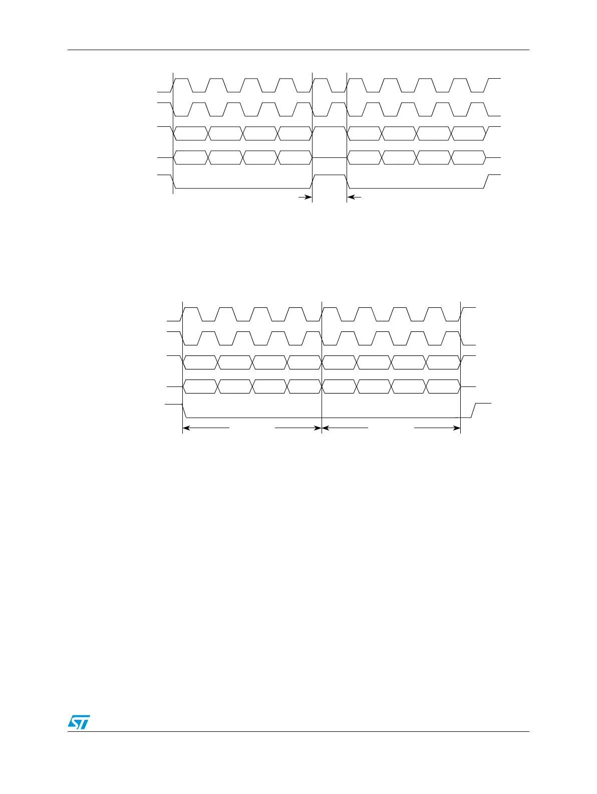
Figure 227. Continuous SCK timing diagram (CONT = 0)
If the CONT bit in the TX FIFO entry is set, CS remains asserted between the transfers
when the CS signal for the next transfer is the same as for the current transfer. Figure 228
shows timing diagram for continuous SCK format with continuous selection enabled.
Figure 228. Continuous SCK timing diagram (CONT = 1)
SCK
(CPOL = 0)
CS
SCK
(CPOL = 1)
Master SOUT
t
DT
t
DT
= 1 SCK.
Master SIN
SCK
(CPOL = 0)
CS
SCK
(CPOL = 1)
Master SOUT
Master SIN
Transfer 1 Transfer 2