Fault Collection Unit (FCU) RM0046
774/936 Doc ID 16912 Rev 5
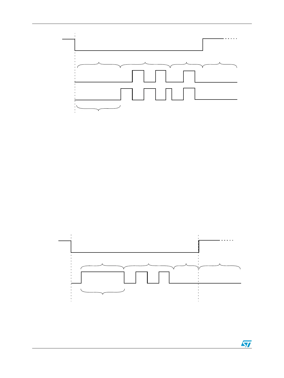
Figure 450. Dual rail coding example
Time switching protocol
FCU[0] is toggled between logic 0 and logic 1 with a defined frequency f = 1 kHz @ 64 MHz
(f is approximated, as shown by Equation 34) and duty cycle d = 50%.
Equation 34
Frequency can be varied by using the same prescaler as used for the dual-rail protocol
(FOP field in FCU_MCR). This frequency modulation protocol is violated when the FCU
goes into Fault state.
During initialization phase, FCU[0] is set high. When a fault is detected, FCU[0] is set low.
Figure 451. Time switching protocol example
Reset
Configuration phase Normal behavior Error occurred
FCU[0]
FCU[1]
During configuration phase
fake faults can be injected
so outputs may be different
Reset is asserted
EOUT freq = SYS_CLK {4096 × [(FOP + 1) × 2]}
64 MHz {4096 × [(7 + 1) × 2]} = 976.5 Hz
Reset
Configuration phase Normal behavior Error occurred
FCU[0]
During configuration phase
fake faults can be injected
so output may be different
Reset is asserted