RM0046 Fault Collection Unit (FCU)
Doc ID 16912 Rev 5 755/936
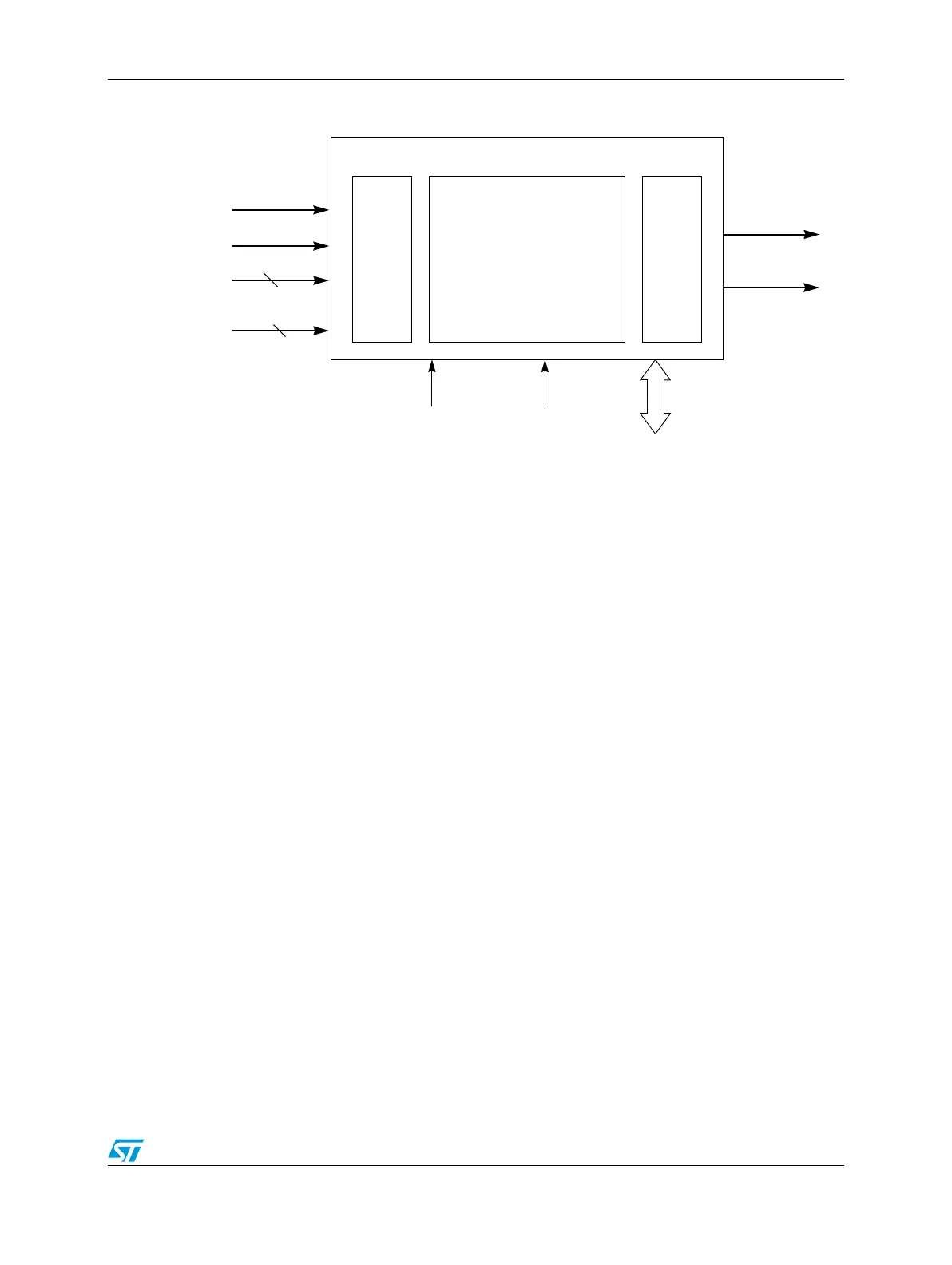
Figure 435. Fault Collection Unit (FCU) block diagram
Figure 436 shows the flow chart of FCU fault handling.
The FCU module and its state machine run on the system clock, making the two modules
synchronous. The high speed RC clock (16 MHz) is used only in the Alarm state, in order to
compute a deterministic timeout.
Input
Unit
Control Unit
(finite state machine)
Output
Unit
Destructive reset
FCU[0]
FCU[1]
32-bit
Fault sources
IPBus
4-bit
Clock/Reset/Power/Mode state
Fault Collection Unit
SYS_CLK IRC_CLK
Functional reset