RM0046 FlexPWM
Doc ID 16912 Rev 5 673/936
Fault Filter Register (FFILT)
The settings in this register are shared among each of the fault input filters.
Table 359. FSTS field descriptions
Field Description
3
FTEST
Fault Test
These read/write bits simulate a fault condition. Setting this bit will cause a simulated fault to be sent
into all of the fault filters. The condition will propagate to the fault flags and possibly the PWM outputs
depending on the DISMAP settings. Clearing this bit removes the simulated fault condition.
0 No fault.
1 Cause a simulated fault.
4:7
FFPIN
Filtered Fault Pins
These read-only bits reflect the current state of the filtered FAULTx pins converted to high polarity. A
logic 1 indicates a fault condition exists on the filtered FAULTx pin. A reset has no effect on FFPIN.
12:15
FFLAG
Fault Flags
These read-only flags are set within 2 CPU cycles after a transition to active on the FAULTx pin.
Clear FFLAGx by writing a logic one to it. A reset clears FFLAG.
0 No fault on the FAULTx pin.
1 Fault on the FAULTx pin.
The FFLAG[3:0] flags will be set out of reset. They should be cleared before enabling the Fault Control
feature.
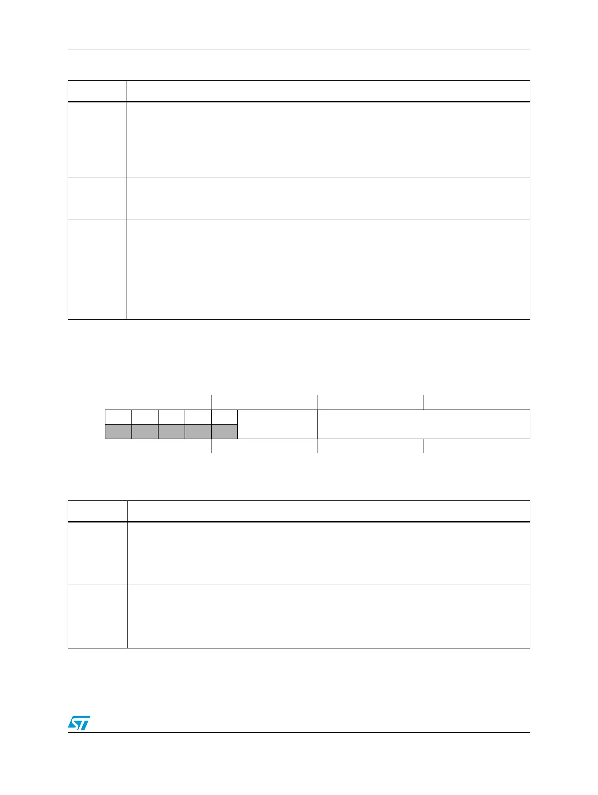
Figure 360. Fault Filter Register (FFILT)
Address:
Base + 0x0150 Access: User read/write
0123456789101112131415
R00000
FILT_CNT FILT_PER
W
Reset0000000000000000
Table 360. FFILT field descriptions
Field Description
5:7
FILT_CNT
Fault Filter Count
These bits represent the number of consecutive samples that must agree prior to the input filter
accepting an input transition. A value of 0 represents 3 samples. A value of 7 represents 10
samples. The value of FILT_CNT affects the input latency as described in Section , “Input filter
considerations.
8:15
FILT_PER
Fault Filter Period
These bits represent the sampling period (in IPBus clock cycles) of the fault pin input filter. Each
input is sampled multiple times at the rate specified by FILT_PER. If FILT_PER is 0x00 (default),
then the input filter is bypassed. The value of FILT_PER affects the input latency as described in
Section , “Input filter considerations.

 Loading...