eTimer RM0046
726/936 Doc ID 16912 Rev 5
Watchdog Time-Out registers (WDTOL and WDTOH)
26.6.4 Configuration registers
The base address of the configuration registers is equal to the base address of the eTimer
plus an offset of 0x010C.
Channel Enable register (ENBL)
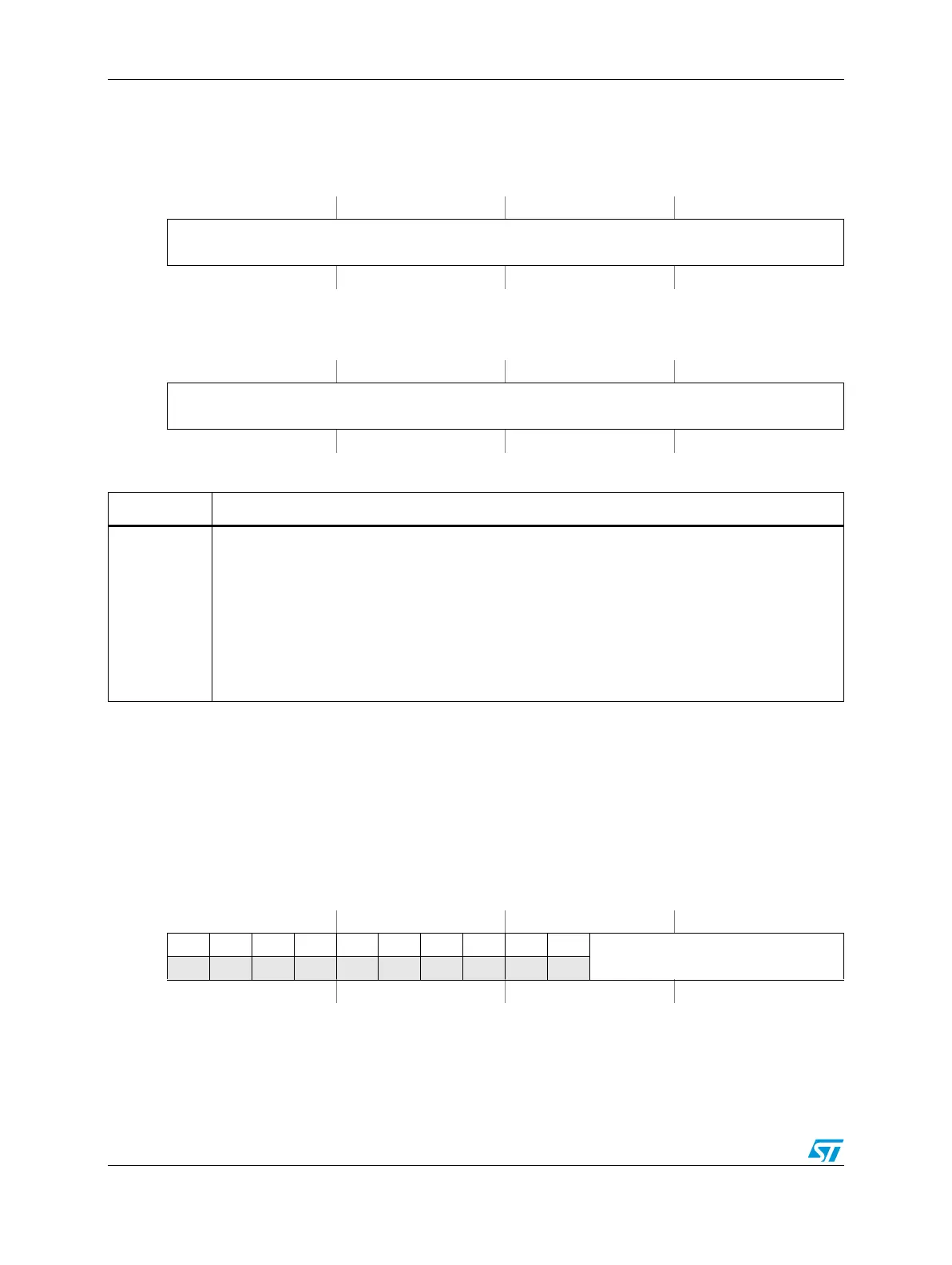
Figure 408. Watchdog Time-out Low Word register (WDTOL)
Address:
Base + 0x0100 Access: User read/write
0123456789101112131415
R
WDTOL
W
Reset0000000000000000
Figure 409. Watchdog Time-Out High Word register (WDTOH)
Address:
Base + 0x0102 Access: User read/write
0123456789101112131415
R
WDTOH
W
Reset0000000000000000
Table 382. WDTOL, WDTOH field descriptions
Field Description
WDTO
Watchdog Time-out
Note: These registers are combined to form the 32-bit time-out count for the Timer
watchdog function. This time-out count is used to monitor for inactivity on the inputs
when channel 0 is in the quadrature decode count mode. The watchdog function is
enabled whenever WDTO contains a non-zero value (although actual counting only
occurs if channel 0 is in quadrature decode counting mode). The watchdog time-out
down counter is loaded whenever WDTOH is written. These registers are not byte
accessible. See Section , “Watchdog timer for more information on the use of the
watchdog timer.
Figure 410. Channel Enable register (ENBL)
Address:
Base + 0x010C Access: User read/write
0123456789101112131415
R00000000 00
ENBL
W
Reset0000000000111111