RM0046 FlexPWM
Doc ID 16912 Rev 5 683/936
25.8.1 PWM clocking
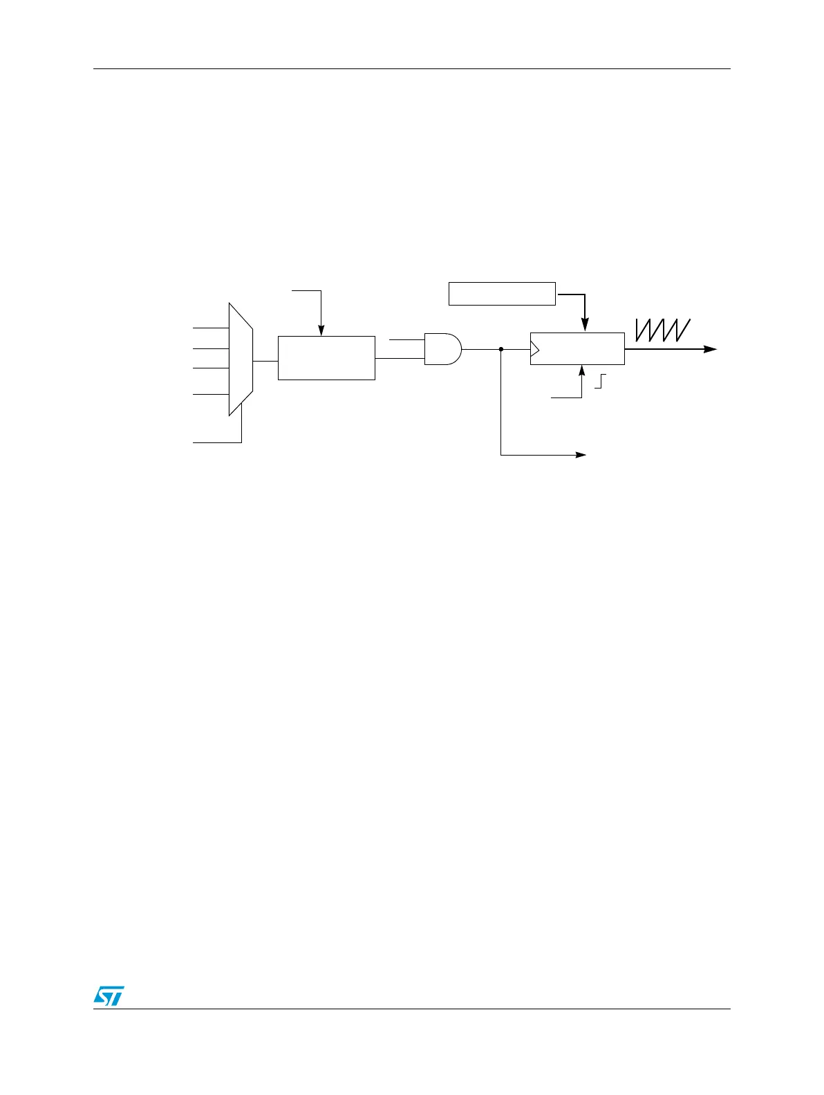
Figure 369 shows the logic used to generate the main counter clock. Each submodule can
select between three clock signals: the IPBus clock, EXT_CLK, and AUX_CLK. The
EXT_CLK is generated by an on-chip resource such as a Timer module and goes to all of
the submodules. The AUX_CLK signal is broadcast from submodule 0 and can be selected
as the clock source by other submodules so that the 8-bit prescaler and RUN bit from
submodule 0 can control all of the submodules. When AUX_CLK is selected as the source
for the submodule clock, the RUN bit from submodule 0 is used instead of the local RUN bit
from this submodule.
Figure 369. Clocking block diagram for each PWM submodule
To permit lower PWM frequencies, the prescaler produces the PWM clock frequency by
dividing the IPBus clock frequency by 1-128. The prescaler bits, PRSC, in the control
register (CTRL1), select the prescaler divisor. This prescaler is buffered and will not be used
by the PWM generator until the LDOK bit is set and a new PWM reload cycle begins.
25.8.2 Register reload logic
The register reload logic determines when the outer set of registers for all double buffered
register pairs will be transferred to the inner set of registers. The register reload event can
be scheduled to occur every n PWM cycles using the LDFQ bits and the FULL bit. A half
cycle reload option is also supported (HALF) where the reload can take place in the middle
of a PWM cycle. The half cycle point is defined by the VAL0 register and does not have to be
exactly in the middle of the PWM cycle.
As illustrated in Figure 370 the reload signal from submodule 0 can be broadcast as the
Master Reload signal allowing the reload logic from submodule 0 to control the reload of
registers in other submodules.
16-bit counter
RUN
8-bit
prescaler
INIT value
IPBus clock
AUX_CLK input
(from submod0)
CLK_SEL
AUX_CLK output
(from submod0 only)
Init
PSRC
Submodule
Clock
0
1
2
3
EXT_CLK
reserved