RM0046 LIN Controller (LINFlex)
Doc ID 16912 Rev 5 525/936
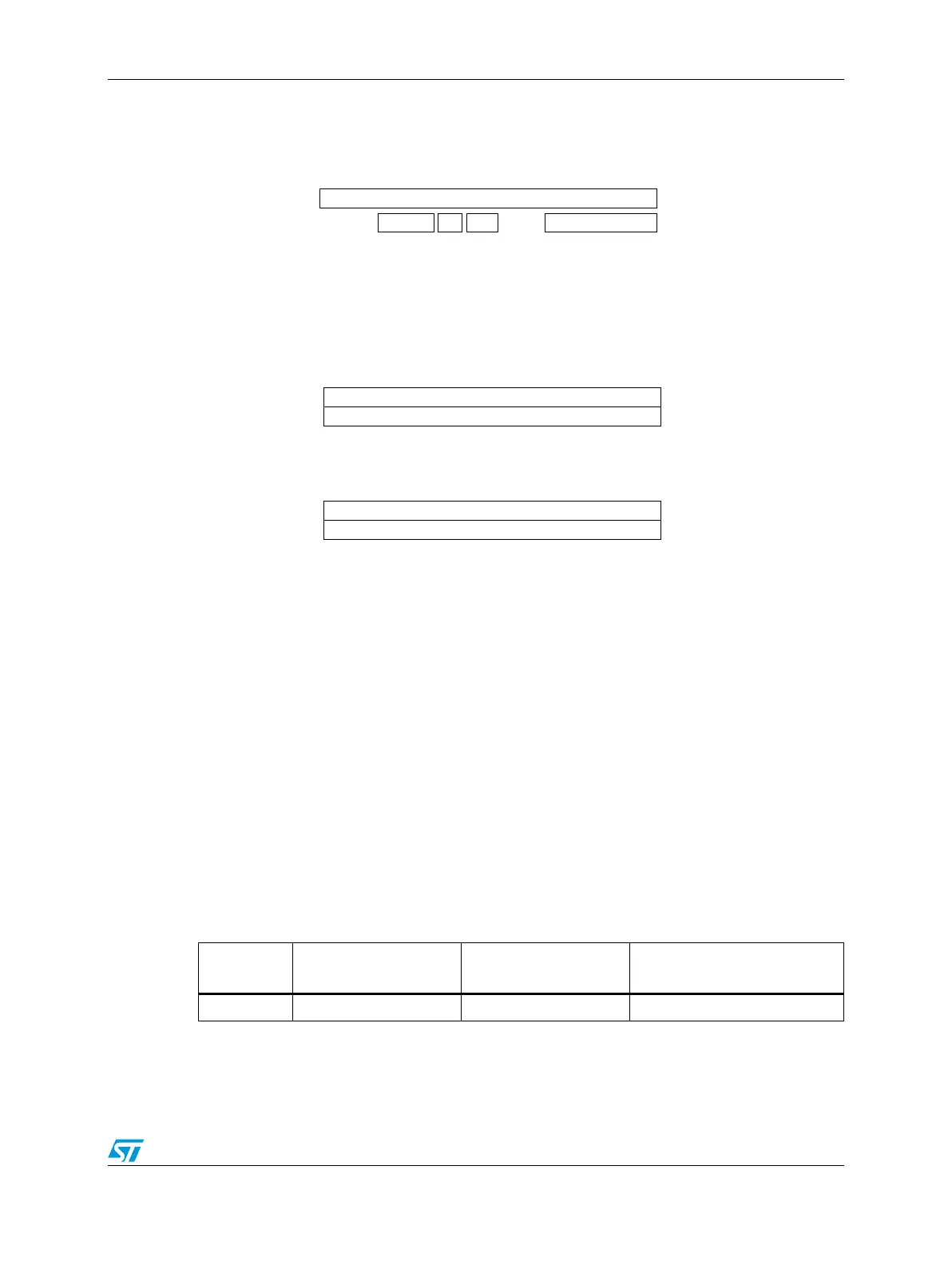
Figure 258. Filter configuration—register organization
Identifier filter mode configuration
The identifier filters are configured in the IFCRx registers. To configure an identifier filter the
filter must first be activated by programming IFER[FACT] = 1. The identifier list or
identifier mask mode for the corresponding IFCRx registers is configured by the IFMR[IFM]
bit. For each filter, the IFCRx register configures the ID (or the mask), the direction (TX or
RX), the data field length, and the checksum type.
If no filter is active, an RX interrupt is generated on any received identifier event.
If at least one active filter is configured as TX, all received identifiers matching this filter
generate a TX interrupt.
If at least one active filter is configured as RX, all received identifiers matching this filter
generate an RX interrupt.
If no active filter is configured as RX, all received identifiers not matching TX filter(s)
generate an RX interrupt.
Table 261. Filter to interrupt vector correlation
Number of
active filters
Number of active filters
configured as TX
Number of active filters
configured as RX
Interrupt vector
0 0 0 RX interrupt on all identifiers
IFCRn
Identifier
ID
Bit Mapping
Identifier Filter Register Organization
15
0
DFL CCSDIR
Identifier Filter Configuration
IFCR2n
Identifier
Identifier
IFCR2n +1
IFM = 0
Identifier Filter Mode
IFCR2n
Identifier
Mask
IFCR2n +1
IFM = 1
Identifier List Mode
Mask Mode