Enhanced Direct Memory Access (eDMA) RM0046
410/936 Doc ID 16912 Rev 5
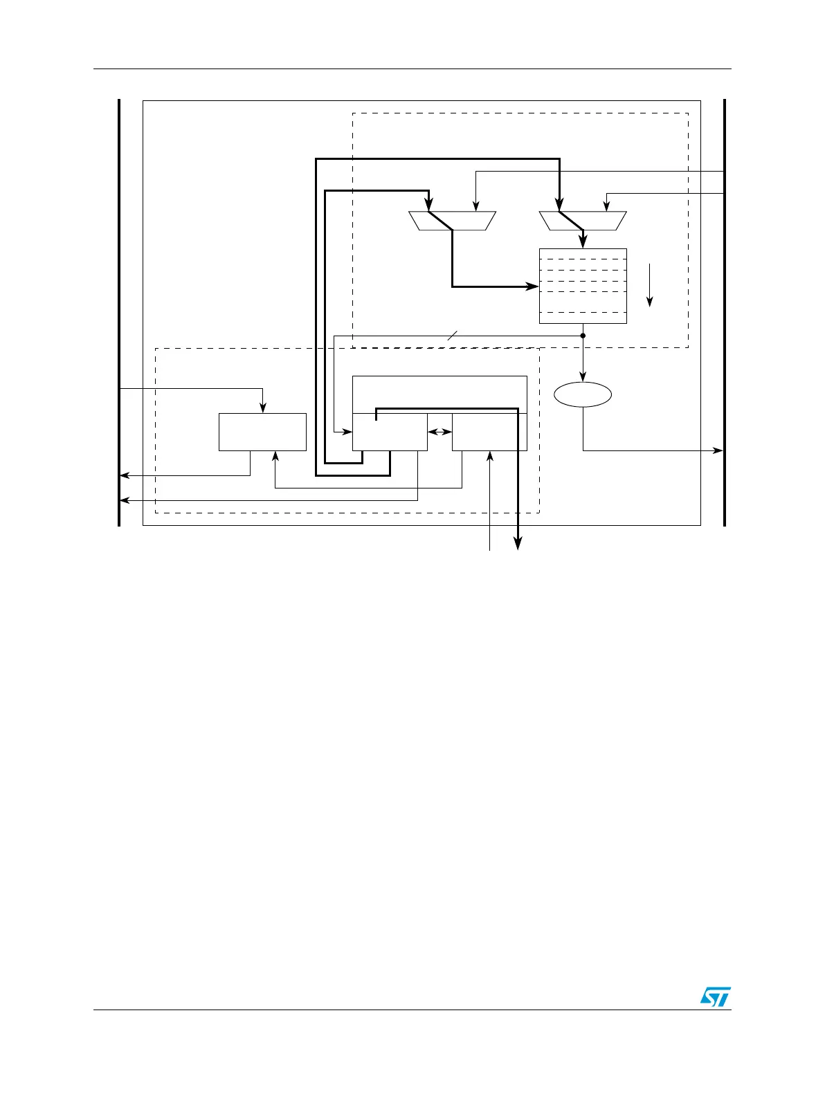
Figure 196. eDMA operation, part 3
18.6.3 eDMA performance
This section addresses the performance of the eDMA module, focusing on two separate
metrics. In the traditional data movement context, performance is best expressed as the
peak data transfer rates achieved using the eDMA. In most implementations, this transfer
rate is limited by the speed of the source and destination address spaces. In a second
context where device-paced movement of single data values to/from peripherals is
dominant, a measure of the requests that can be serviced in a fixed time is a more useful
metric. In this environment, the speed of the source and destination address spaces
remains important, but the microarchitecture of the eDMA also factors significantly into the
resulting metric.
The peak transfer rates for several different source and destination transfers are shown in
Table 194. The following assumptions apply to Table 1 94 and Tabl e 19 5 :
● Internal SRAM can be accessed with zero wait-states when viewed from the system
bus data phase.
● All slave reads require two wait-states, and slave writes three wait-states, again viewed
from the system bus data phase.
● All slave accesses are 32-bits in size.
Slave Interface
eDMA
eDMA Done
System Bus
Slave Write Data
Slave Write Address
Bus Write Data
Slave Read Data
Bus Address
eDMA Engine
TCD0
TCDn –1*
eDMA Peripheral
Bus Read Data
Request
SRAM
Transfer Control Descriptor
(TCD)
SRAM
Data Path
Address
Path
Control
Program Model/
Channel Arbitration
*n = 16 channels