RM0046 Cross Triggering Unit (CTU)
Doc ID 16912 Rev 5 631/936
24.8.10 Commands list register x (x = 1,...,24) (CLRx)
Figure 318 and Table 3 2 6 show the register configured for ADC command format in single
conversion mode (CMS = 0) (CLRx).
Figure 319 and Table 3 2 7 show the register configured for ADC command format in dual
conversion mode (CMS = 1).
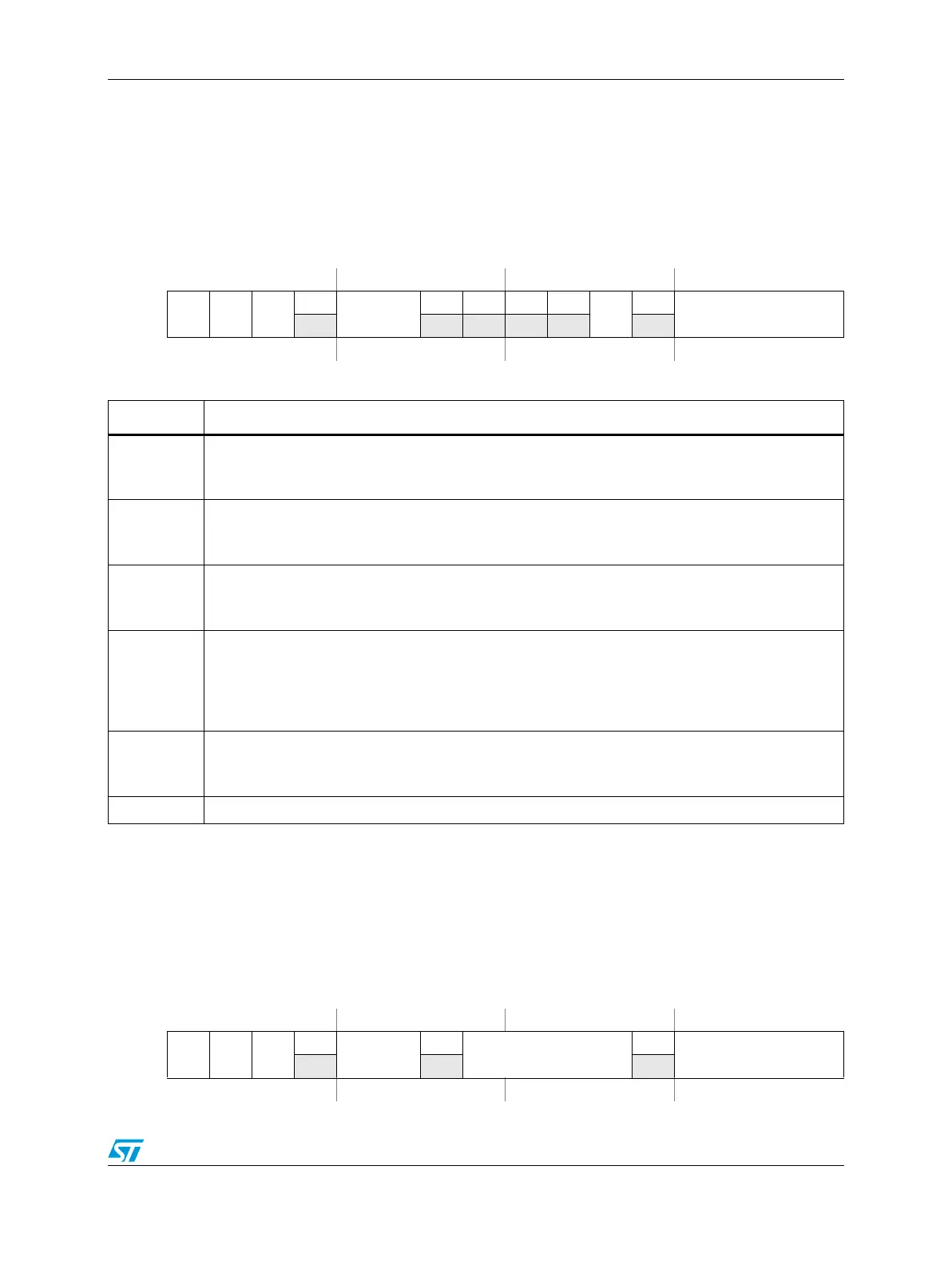
Figure 318. Commands list register x (x = 1,...,24) (CMS = 0)
Address:
Base + 0x002C,...,0x005A
(See Table 312)
Access: User read/write
0123456789101112131415
R
CIR FC CMS
0
FIFO
0 0 00
SU
0
CH
W
Reset0000000000000000
Table 326. CLRx (CMS = 0) field descriptions
Field Description
CIR
Command Interrupt Request bit
0 Disabled
1 Enabled
FC
First command bit
0 Not first command
1 First command
CMS
Conversion mode selection bit
0 Single conversion mode
1 Dual conversion mode
FIFO
FIFO for ADC unit 0/1
00 FIFO 0 selected
01 FIFO 1 selected
10 FIFO 2 selected
11 FIFO 3 selected
SU
Selection Unit bit
0 ADC unit 0 selected
1 ADC unit 1 selected
CH ADC unit channel number
Figure 319. Commands list register x (x = 1,...,24) (CMS = 1)
Address:
Base + 0x002C ... 0x005A
(See Table 312)
Access: User read/write
0123456789101112131415
R
CIR FC CMS
0
FIFO
0
CH_B
0
CH_A
W
Reset0000000000000000