RM0046 Cyclic Redundancy Check (CRC)
Doc ID 16912 Rev 5 797/936
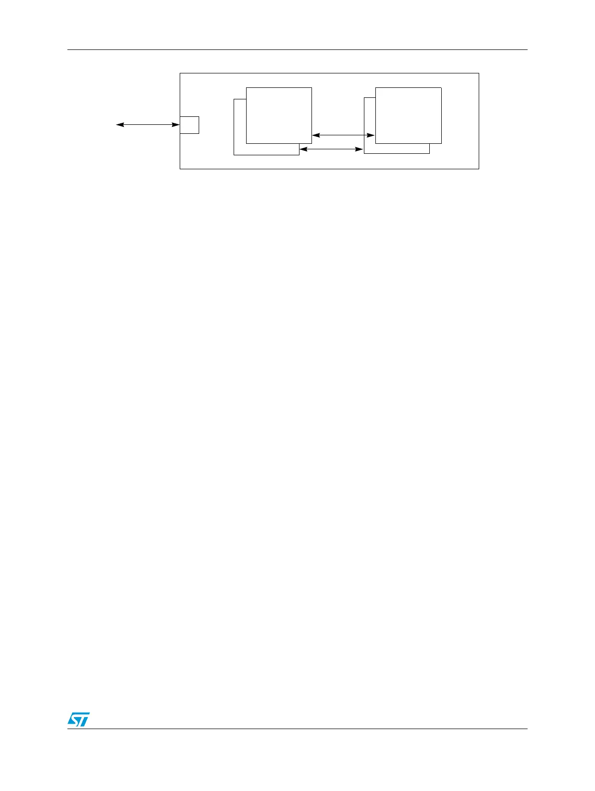
Figure 470. CRC top level diagram
32.3.1 IPS bus interface
The IPS bus interface is a slave bus used for configuration and data streaming (CRC
computation) purposes via CPU or DMA. The following bus operations (contiguous byte
enables) are supported:
● Word (32-bit) data write/read operations to any registers
● Low and high half-words (16-bit, data[31:16] or data[15:0]) data write/read operations
to any registers
● Byte (8-bit, data[31:24] or data[23:16] or data[15:8] or data[7:0]) data write/read
operations to any registers
● Any other operation (free byte enables or other operations) must be avoided.
The CRC generates a transfer error in the following cases:
● Any write/read access to the register addresses not mapped on the peripheral but
included in the address space of the peripheral.
● Any write/read operation different from byte/hword/word (free byte enables or other
operations) on each register.
The registers of the CRC module are accessible (read/write) in each access mode: user,
supervisor, or test.
In terms of bus performance of the operations, following the summary:
● 0 WS (single bus cycle) for each write/read operations to the CRC_CFG and CRC_INP
registers
● 0 WS (single bus cycle) for each write operation to the CRC_ CSTAT register
● Double WS (3 bus cycles) for each read operation to the CRC_ CSTAT or CRC_OUTP
registers immediately following (next clock cycle) a write operation to the CRC_CSTAT,
CRC_INP or CRC_CFG registers belonging to the same context. In all the other cases
no WS are inserted.
32.4 Functional description
The CRC module supports the CRC computation for each context. Each context has a own
complete set of registers including the CRC engine. The data flow of each context can be
interleaved. The data stream can be structured as a sequence of byte, half-words or words.
The input data sequence is provided, eventually mixing the data formats (byte, half-word,
word), writing to the input data register (CRC_INP).
CRC
Engine
context 2
and
context 2
Config and
Data Registers
context 1
CRC
Engine
context 1
S
IPS