Boot Assist Module (BAM) RM0046
822/936 Doc ID 16912 Rev 5
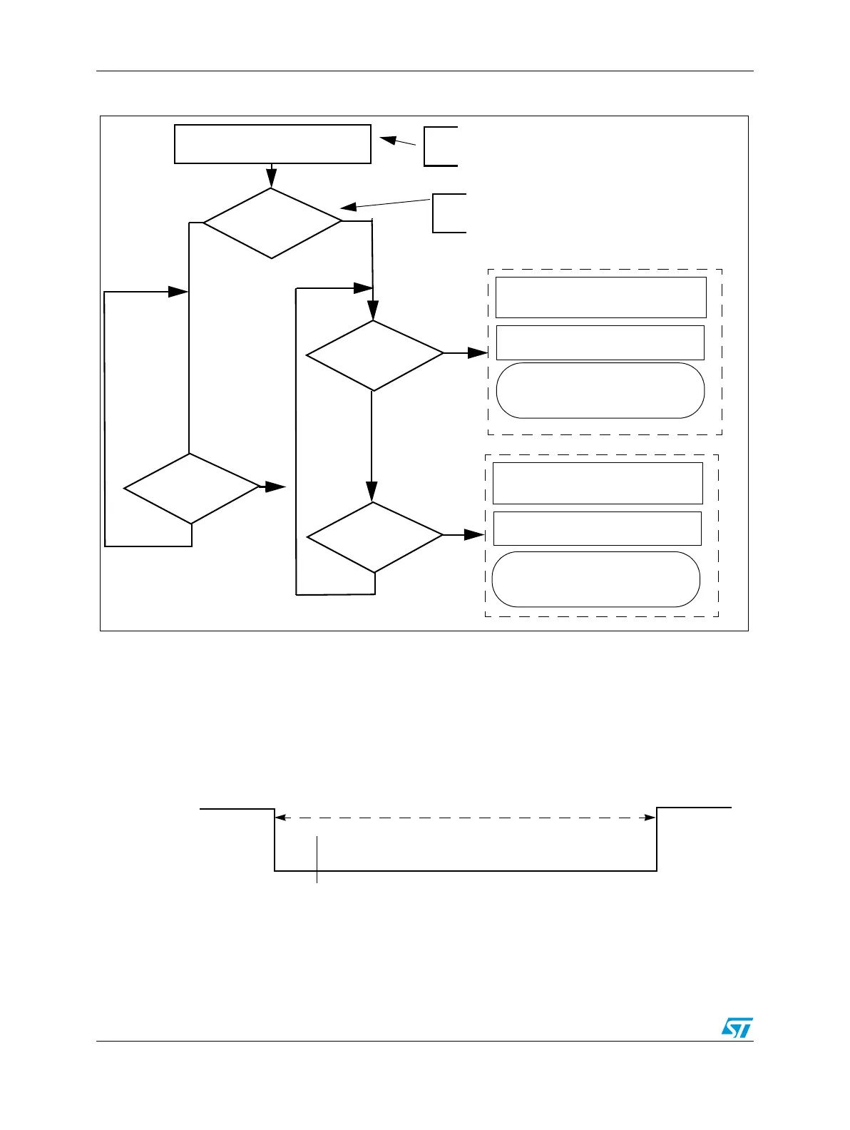
Figure 487. BAM Autoscan code flow
Boot from UART with autobaud enabled
The only difference between booting from UART with autobaud enabled and booting from
UART with autobaud disabled is that a further byte is sent from the host to the MCU when
autobaud is enabled. The value of that byte is 0x00.
This first byte measures the time from falling edge and rising edge. The baud rate can be
calculated from this time.
Figure 488. Baud measurement on UART boot
Initially the UART RX pin is configured as GPIO input and it waits in polling for the first falling
edge, then STM starts. UART RX pin waits again for the first rising. Then STM stops and
from its measurement baud rate is computed.
FlexCAN RX and LINFlex RX
configured as GPIO inputs
FlexCAN RX
== 1
FlexCAN RX
== 0
LINFlex RX
== 0
CAN Autobaud
Set matching baud rate
for FlexCAN
Autobaud measurement
Continue with FlexCAN
LINFlex Autobaud
Set matching baud rate
for LINFlex
Autobaud measurement
download
Continue with LINFlex
download
NO
YES
detected
detected
LINFlex RX
== 0
detected
Both RDX pins have to be at high level.
Avoid to connect them to external pull-down resistor.
If CAN is connected, after reset CAN_RX has to be
at high level
Time measurement
Start
0x0
bit