FlexPWM RM0046
682/936 Doc ID 16912 Rev 5
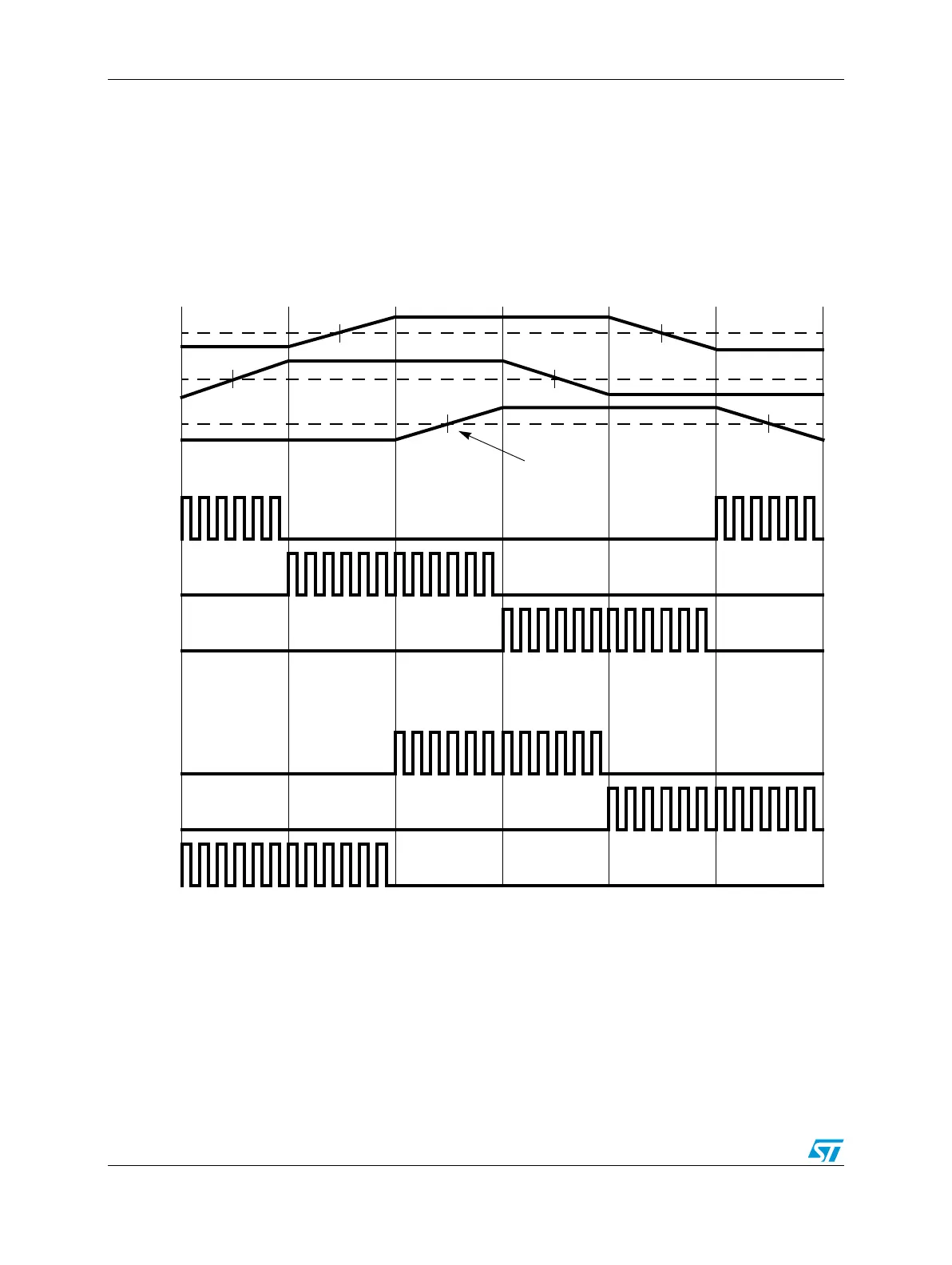
simplistic representation of these back EMF signals. Timer compare events (represented by
the long vertical lines in the diagram) are scheduled based on the zero crossings of the
back-EMF waveforms. The PWM module is configured via software ahead of time with the
next state of the PWM pins in anticipation of the compare event. When it happens, the
output compare of the timer drives the FORCE_OUT signal, which immediately changes the
state of the PWM pins to the next commutation state with no software latency.
Figure 368. Sensorless BLDC commutation using the force out function
25.8 Functional details
This section describes the implementation of various features of the PWM in greater detail.
Rotor Electrical Position (degrees)
0
60 120 180 240 300 360
Phase R
Phase S
Phase T
PWMA0
PWMA1
PWMA2
PWMB0
PWMB1
PWMB2
zero
crossings