Mode Entry Module (MC_ME) RM0046
150/936 Doc ID 16912 Rev 5
Mode Enable Register (ME_ME)
This register allows a way to disable the device modes which are not required for a given
device. RESET, SAFE, DRUN, and RUN0 modes are always enabled.
Table 40. Mode Control Register (ME_MCTL) Field Descriptions
Field Description
TA R G ET_ MO D E
Target device mode — These bits provide the target device mode to be entered by software
programming. The mechanism to enter into any mode by software requires the write operation
twice: first time with key, and second time with inverted key. These bits are automatically
updated by hardware while entering SAFE on hardware request. Also, while exiting from the
HALT0 and STOP0 modes on hardware exit events, these are updated with the appropriate
RUN0…3 mode value.
0000 RESET
0001 TEST
0010 SAFE
0011 DRUN
0100 RUN0
0101 RUN1
0110 RUN2
0111 RUN3
1000 HALT0
1001 reserved
1010 STOP0
1011 reserved
1100 reserved
1101 reserved
1110 reserved
1111 reserved
KEY
Control key — These bits enable write access to this register. Any write access to the register
with a value different from the keys is ignored. Read access will always return inverted key.
KEY:0101101011110000 (0x5AF0)
INVERTED KEY:1010010100001111 (0xA50F)
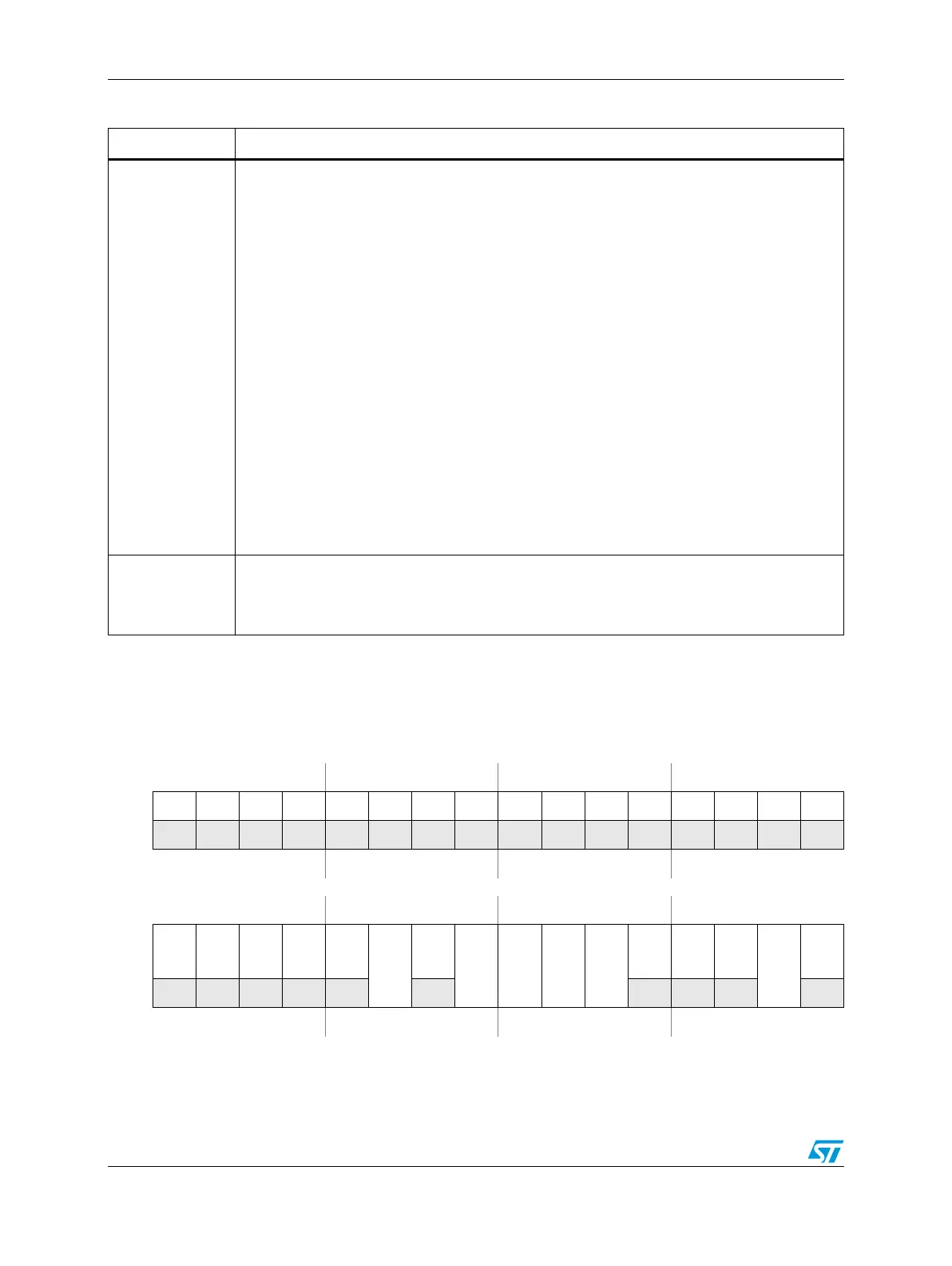
Figure 45. Mode Enable Register (ME_ME)
Address 0xC3FD_C008 Access: User read, Supervisor read/write, Test read/write
0123456789101112131415
R0000000000000000
W
Reset0000000000000000
16 17 18 19 20 21 22 23 24 25 26 27 28 29 30 31
R00000
STOP0
0
HALT0
RUN3
RUN2
RUN1
RUN0
DRUN
SAFE
TEST
RESET
W
Reset0000000000011101