Mode Entry Module (MC_ME) RM0046
162/936 Doc ID 16912 Rev 5
This register configures system behavior during HALT0 mode. Please refer to Tabl e 4 6 for
details.
Note: Byte write accesses are not allowed to this register.
Note: The reset value of the DFLAON field in the ME_HALT0_MC register is “10”. This reset value
is illegal for the data flash. Thus, the reset value for the HALT0 mode configuration cannot
be used as is and must be set to a legal value before requesting the entry of the HALT0
mode.
STOP0 Mode Configuration Register (ME_STOP0_MC)
This register configures system behavior during STOP0 mode. Please refer to Table 4 6 for
details.
Note: Byte write accesses are not allowed to this register.
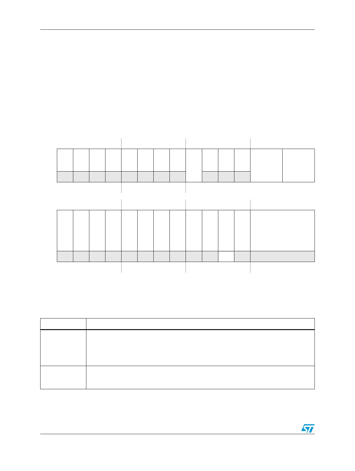
Figure 56. STOP0 Mode Configuration Register (ME_STOP0_MC)
Address 0xC3FD_C048 Access: User read, Supervisor read/write, Test read/write
0123456789101112131415
R00000000
PDO
00
MVRON
DFLAON CFLAON
W
Reset0000000000010101
16 17 18 19 20 21 22 23 24 25 26 27 28 29 30 31
R000000000
PLL0ON
XOSC0ON
16 MHz_IRCON
SYSCLK
W
Reset0000000000010000
Table 46. Mode Configuration Registers (ME_<mode>_MC) Field Descriptions
Field Description
PDO
I/O output power-down control — This bit controls the output power-down of I/Os.
0 No automatic safe gating of I/Os used and pads power sequence driver is enabled
1 In SAFE/TEST modes, outputs of pads are forced to high impedance state and pads power
sequence driver is disabled. The inputs are level unchanged. In STOP0 mode, only the pad
power sequence driver is disabled, but the state of the output remains functional.
MVRON
Main voltage regulator control — This bit specifies whether main voltage regulator is switched
off or not while entering this mode.
1 Main voltage regulator is switched on