RM0046 FlexPWM
Doc ID 16912 Rev 5 667/936
Note: The MASKx bits are double buffered and do not take effect until a FORCE_OUT event
occurs within the appropriate submodule. Refer to Figure 373 to see how FORCE_OUT is
generated. Reading the MASK bits reads the buffered value and not necessarily the value
currently in effect.
Software Controlled Output Register (SWCOUT)
.
8:11
MASKB[3:0]
PWMB Masks
These bits mask the PWMB outputs of each submodule forcing the output to logic 0 prior to
consideration of the output polarity.
0 PWMB output normal.
1 PWMB output masked.
12:15
MASKX[3:0]
PWMX Masks
These bits mask the PWMX outputs of each submodule forcing the output to logic 0 prior to
consideration of the output polarity.
0 PWMX output normal.
1 PWMX output masked.
Table 354. MASK field descriptions (continued)
Field Description
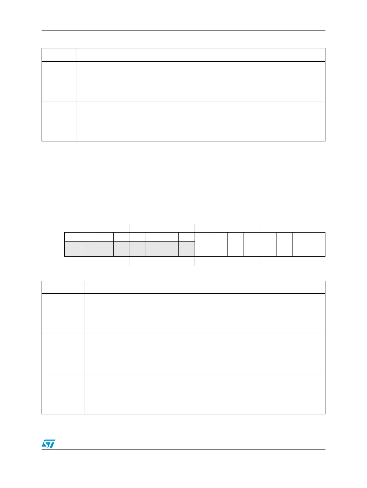
Figure 355. Software Controlled Output Register (SWCOUT)
Address:
Base + 0x0144 Access: User read/write
0123456789101112131415
R00000000
OUTA_3
OUTB_3
OUTA_2
OUTB_2
OUTA_1
OUTB_1
OUTA_0
OUTB_0
W
Reset0000000000000000
Table 355. SWCOUT field descriptions
Field Description
8
OUTA_3
Software Controlled Output A_3
This bit is only used when SELA for submodule 3 is set to 0b10. It allows software control of which
signal is supplied to the deadtime generator of that submodule.
0 A logic 0 is supplied to the deadtime generator of submodule 3 instead of PWMA.
1 A logic 1 is supplied to the deadtime generator of submodule 3 instead of PWMA.
9
OUTB_3
Software Controlled Output B_3
This bit is only used when SELB for submodule 3 is set to 0b10. It allows software control of which
signal is supplied to the deadtime generator of that submodule.
0 A logic 0 is supplied to the deadtime generator of submodule 3 instead of PWMB.
1 A logic 1 is supplied to the deadtime generator of submodule 3 instead of PWMB.
10
OUTA_2
Software Controlled Output A_2
This bit is only used when SELA for submodule 2 is set to 0b10. It allows software control of which
signal is supplied to the deadtime generator of that submodule.
0 A logic 0 is supplied to the deadtime generator of submodule 2 instead of PWMA.
1 A logic 1 is supplied to the deadtime generator of submodule 2 instead of PWMA.