Enhanced Direct Memory Access (eDMA) RM0046
414/936 Doc ID 16912 Rev 5
request rate calculations above, the arbitration and request registering is absorbed in or
overlap the previous executing channel.
Note: When channel linking or scatter/gather is enabled, a two-cycle delay is imposed on the next
channel selection and startup. This allows the link channel or the scatter/gather channel to
be eligible and considered in the arbitration pool for next channel selection.
18.7 Initialization / application information
18.7.1 eDMA initialization
A typical initialization of the eDMA has the following sequence:
1. Write the EDMA_CR if a configuration other than the default is desired.
2. Write the channel priority levels into the EDMA_CPRn registers if a configuration other
than the default is desired.
3. Enable error interrupts in the EDMA_EEIRL and/or EDMA_EEIRH registers (optional).
4. Write the 32-byte TCD for each channel that can request service.
5. Enable any hardware service requests via the EDMA_ERQRH and/or EDMA_ERQRL
registers.
6. Request channel service by either software (setting the TCD.START bit) or by hardware
(slave device asserting its eDMA peripheral request signal).
After any channel requests service, a channel is selected for execution based on the
arbitration and priority levels written into the programmer's model. The eDMA engine reads
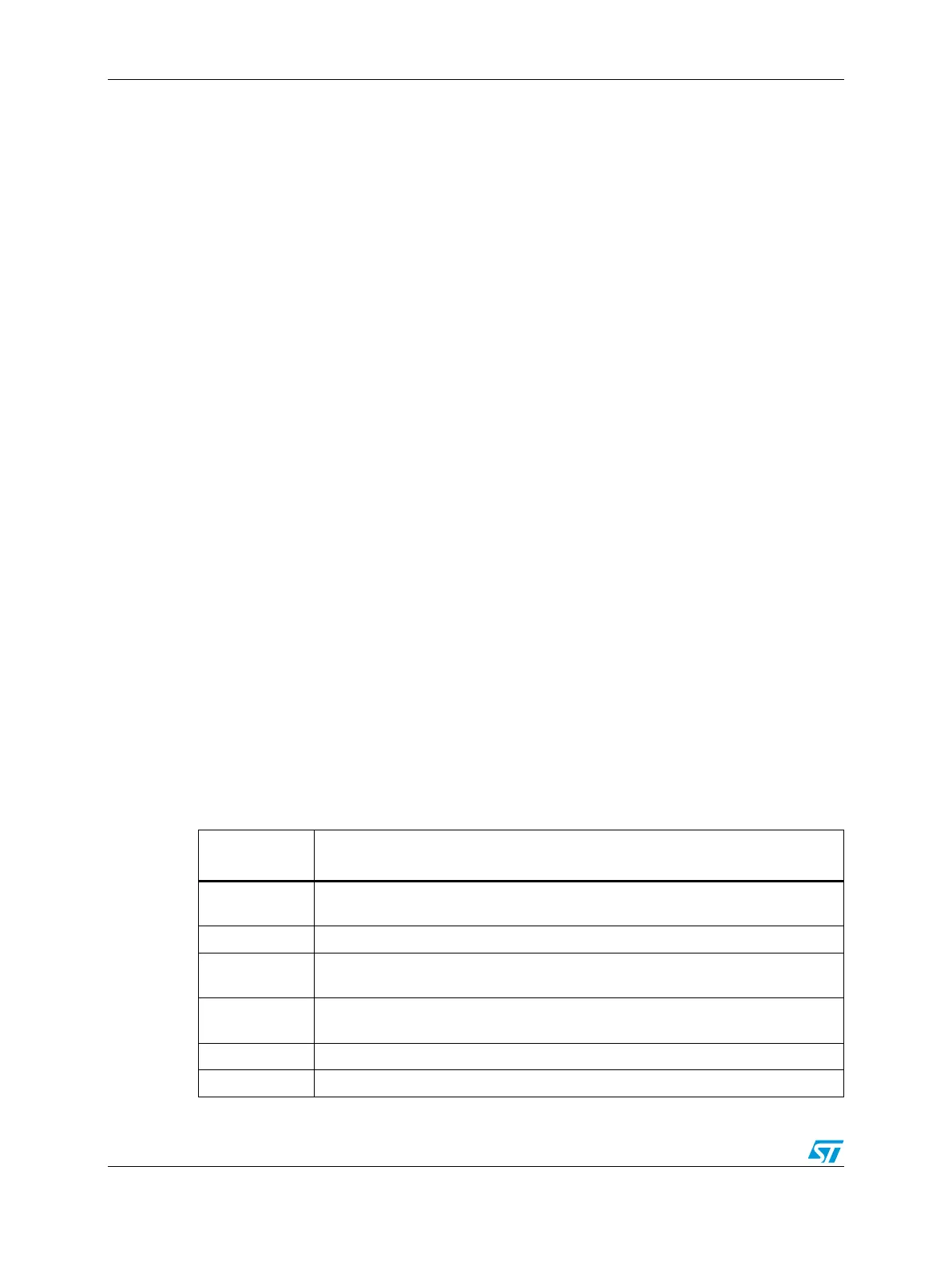
the entire TCD, including the primary transfer control parameter shown in Table 196 , for the
selected channel into its internal address path module. As the TCD is being read, the first
transfer is initiated on the system bus unless a configuration error is detected. Transfers
from the source (as defined by the source address, TCD.SADDR) to the destination (as
defined by the destination address, TCD.DADDR) continue until the specified number of
bytes (TCD.NBYTES) have been transferred. When the transfer is complete, the eDMA
engine's local TCD.SADDR, TCD.DADDR, and TCD.CITER are written back to the main
TCD memory and any minor loop channel linking is performed, if enabled. If the major loop
is exhausted, further post processing is executed: for example, interrupts, major loop
channel linking, and scatter/gather operations, if enabled.
Table 196. TCD primary control and status fields
TCD Field
Name
Description
START
Control bit to explicitly start channel when using a software initiated DMA service
(Automatically cleared by hardware)
ACTIVE Status bit indicating the channel is currently in execution
DONE
Status bit indicating major loop completion (Cleared by software when using a
software initiated DMA service)
D_REQ
Control bit to disable DMA request at end of major loop completion when using a
hardware-initiated DMA service
BWC Control bits for “throttling” bandwidth control of a channel
E_SG Control bit to enable scatter-gather feature

 Loading...