RM0046 Analog-to-Digital Converter (ADC)
Doc ID 16912 Rev 5 597/936
23.4.5 Threshold registers
Introduction
The Threshold registers store the user programmable lower and upper thresholds’ values.
The inverter bit and the mask bit for mask the interrupt are stored in the TRC registers.
Threshold Control Register (TRCx, x = [0..3])
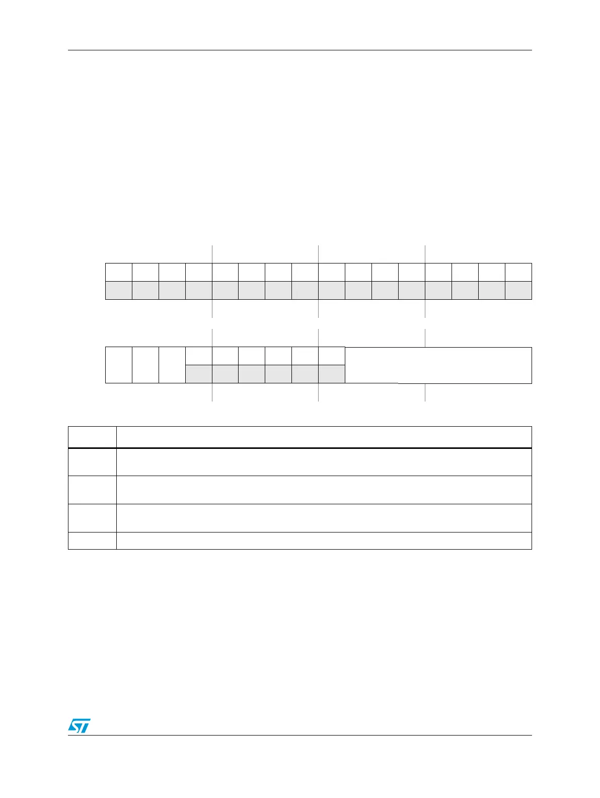
Figure 294. Threshold Control Register (TRCx, x = [0..3])
Address:
Base + 0x0050 (TRC0)
Base + 0x0054 (TRC1)
Base + 0x0058 (TRC2)
Base + 0x005C (TRC3) Access: User read/write
0123456789101112131415
R00000000 00000 000
W
Reset0000000000000000
16 17 18 19 20 21 22 23 24 25 26 27 28 29 30 31
R
THR
EN
THR
INV
THR
OP
0000
0 0
THRCH
W
Reset0000000000000000
Table 303. TRCx field descriptions
Field Description
THREN
Threshold enable
When set, this bit enables the threshold detection feature for the selected channel.
THRINV
Invert the output pin
Setting this bit inverts the behavior of the threshold output pin.
THROP
This bit reflects the output pin status. See Section , Analog watchdog functionality.” It reflects the output
pin status.
THRCH Choose the channel for threshold comparison.