RM0046 Enhanced Direct Memory Access (eDMA)
Doc ID 16912 Rev 5 399/936
The following table describes the fields in the eDMA channel n priority register:
Transfer Control Descriptor (TCD)
Each channel requires a 256-bit transfer control descriptor for defining the desired data
movement operation. The channel descriptors are stored in the local memory in sequential
order: channel 0, channel 1,... channel 15. The definitions of the TCD are presented as 23
variable-length fields.
Table 192 defines the fields of the basic TCD structure.
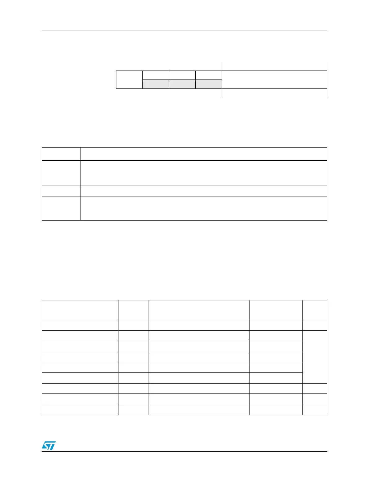
Figure 192. eDMA Channel n Priority Register (EDMA_CPRn)
Address: Base + 0x100 + n Access: User read/write
01234567
R
ECP
000
CHPRI
W
Reset0000 —
1
1. The reset value for the channel priority fields, GRPPRI[0–1] and CHPRI[0–3] is the
channel number for the priority register;
EDMA_CPR15[CHPRI] = 0b1111.
Table 191. EDMA_CPRn field descriptions
Field Description
0
ECP
Enable channel preemption.
0 Channel n cannot be suspended by a higher priority channel’s service request.
1 Channel n can be temporarily suspended by the service request of a higher priority channel.
1-3 Reserved.
4–7
CHPRI[0:3]
Channel n arbitration priority. Channel priority when fixed-priority arbitration is enabled. The reset
value for the channel priority fields CHPRI[0–3], is equal to the corresponding channel number for
each priority register; that is, EDMA_CPR31[CHPRI] = 0b1111.
Table 192. TCDn 32-bit memory structure
eDMA Bit Offset
Bit
Length
TCDn Field Name
TCDn
Abbreviation
Word #
0x1000 + (32 × n) + 0 32 Source address SADDR Word 0
0x1000 + (32 × n) + 32 5 Source address modulo SMOD
Word 1
0x1000 + (32 × n) + 37 3 Source data transfer size SSIZE
0x1000 + (32 × n) + 40 5 Destination address modulo DMOD
0x1000 + (32 × n) + 45 3 Destination data transfer size DSIZE
0x1000 + (32 × n) + 48 16 Signed Source Address Offset SOFF
0x1000 + (32 × n) + 64 32 Inner minor byte count NBYTES Word 2
0x1000 + (32 × n) + 96 32 Last Source Address Adjustment SLAST Word 3
0x1000 + (32 × n) + 128 32 Destination Address DADDR Word 4