Deserial Serial Peripheral Interface (DSPI) RM0046
474/936 Doc ID 16912 Rev 5
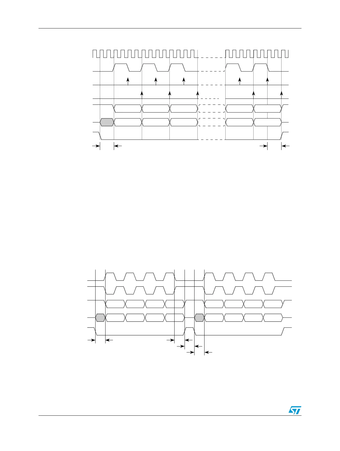
Figure 223. DSPI modified transfer format (MTFE = 1, CPHA = 1, f
SCK
= f
SYS
/ 4)
Continuous selection format
Some peripherals must be deselected between every transfer. Other peripherals must
remain selected between several sequential serial transfers. The continuous selection
format provides the flexibility to handle both cases. The continuous selection format is
enabled for the SPI configuration by setting the CONT bit in the SPI command.
When the CONT bit = 0, the DSPI drives the asserted chip select signals to their idle states
in between frames. The idle states of the chip select signals are selected by the PCSIS field
in the DSPIx_MCR.
Figure 224 shows the timing diagram for two 4-bit transfers with CPHA = 1 and CONT = 0.
Figure 224. Example of non-continuous format (CPHA = 1, CONT = 0)
t
CSC
= CS to SCK delay.
t
ASC
= After SCK delay.
System clock
123456
CS
t
ASC
SCK
Master sample
Master SOUT
Slave SOUT
Slave sample
t
CSC
SCK
(CPOL = 0)
CSx
t
ASC
SCK
(CPOL = 1)
Master SOUT
t
DT
t
CSC
t
CSC
= CS to SCK delay.
t
ASC
= After SCK delay.
t
DT
= Delay after transfer (minimum CS negation time).
Master SIN
t
CSC