FlexPWM RM0046
670/936 Doc ID 16912 Rev 5
Note: The deadtime source select bits are double buffered and do not take effect until a
FORCE_OUT event occurs within the appropriate submodule. Refer to Figure 373 to see
how FORCE_OUT is generated. Reading these bits reads the buffered value and not
necessarily the value currently in effect.
Master Control Register (MCTRL)
The relationship between the fields of MCTRL and the submodules is as follows:
– Field[3] refers to submodule 3
– Field[2] refers to submodule 2
– Field[1] refers to submodule 1
– Field[0] refers to submodule 0
12:13
SELA_0
PWMA_0 Control Select
This field selects possible over-rides to the generated PWMA signal in submodule 0 that will be
passed to the deadtime logic upon the occurrence of a “Force Out” event in that submodule.
00 Generated PWMA_0 signal is used by the deadtime logic.
01 Inverted generated PWMA_0 signal is used by the deadtime logic.
10 OUTA_0 bit is used by the deadtime logic.
11 Reserved
14:15
SELB_0
PWMB_0 Control Select
This field selects possible over-rides to the generated PWMB signal in submodule 0 that will be
passed to the deadtime logic upon the occurrence of a “Force Out” event in that submodule.
00 Generated PWMB_0 signal is used by the deadtime logic.
01 Inverted generated PWMB_0 signal is used by the deadtime logic.
10 OUTB_0 bit is used by the deadtime logic.
11 Reserved
Table 356. DTSRCSEL field descriptions (continued)
Field Description
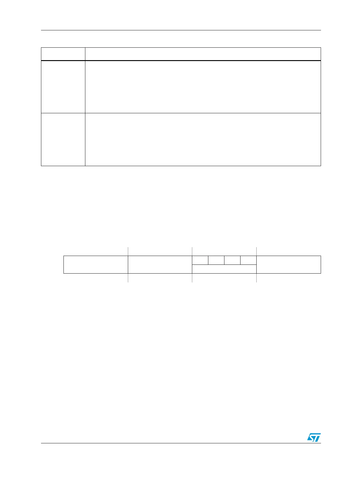
Figure 357. Master Control Register (MCTRL)
Address:
Base + 0x0148 Access: User read/write
0123456789101112131415
R
IPOL RUN
0000
LDOK
WCLDOK
Reset0000000000000000