RM0046 Crossbar Switch (XBAR)
Doc ID 16912 Rev 5 281/936
14 Crossbar Switch (XBAR)
14.1 Introduction
This chapter describes the multi-port crossbar switch (XBAR), which supports simultaneous
connections between three master ports and three slave ports. XBAR supports a 32-bit
address bus width and a 32-bit data bus width at all master and slave ports.
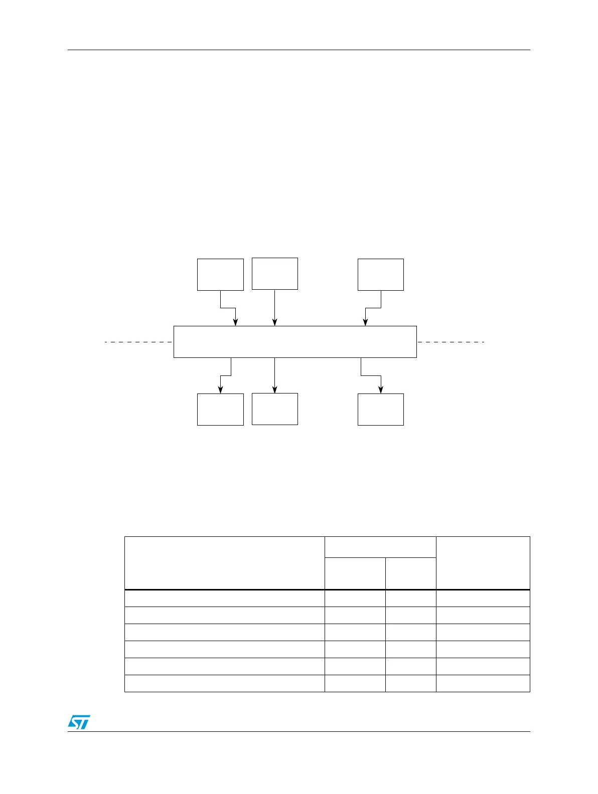
14.2 Block diagram
Figure 122 shows a block diagram of the crossbar switch.
Figure 122. XBAR block diagram
Table 110 gives the crossbar switch port for each master and slave, the assigned and fixed
ID number for each master and shows the master ID numbers as they relate to the master
port numbers.
Master
Crossbar Switch
Slave
Master modules
Slave modules
Master Master
Slave Slave
. . . .
. . . .
Table 110. Device XBAR switch ports
Module
Port
Physical master ID
Type
Logical
number
e200z0 core—CPU instructions Master 0 0
e200z0 core—Data Master 0 1
eDMA Master 2 2
Flash Controller Slave 0 —
Internal SRAM Controller Slave 2 —
Peripheral bridge Slave 7 —