RM0046 FlexPWM
Doc ID 16912 Rev 5 695/936
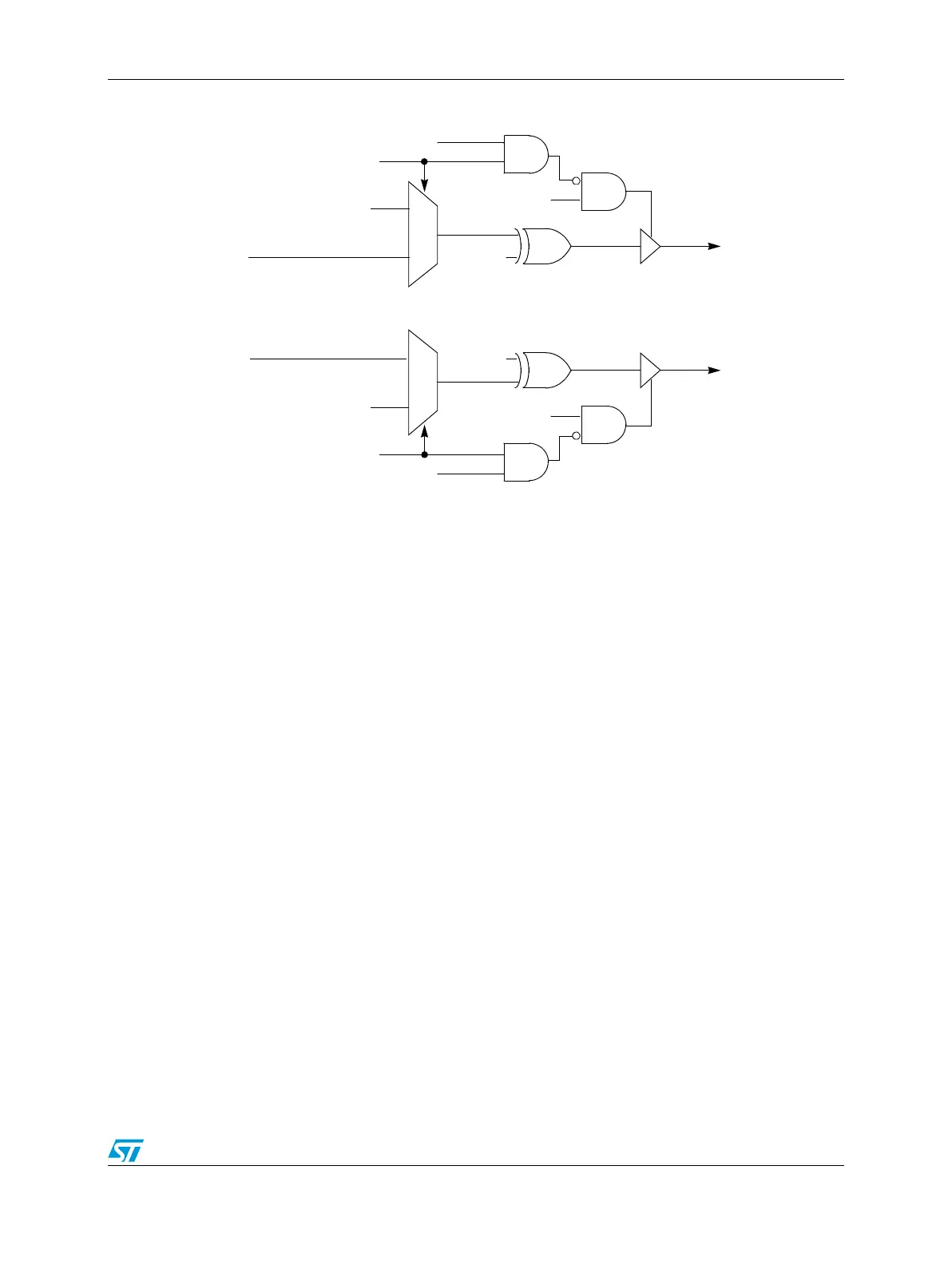
Figure 381. Output logic section
25.8.12 Fault protection
Fault protection can control any combination of PWM output pins. Faults are generated by a
logic one on any of the FAULTx pins. This polarity can be changed via the FLVL bits. Each
FAULTx pin can be mapped arbitrarily to any of the PWM outputs. When fault protection
hardware disables PWM outputs, the PWM generator continues to run, only the output pins
are forced to logic 0, logic 1, or tristated depending the values of the PWMxFS bits.
The fault decoder disables PWM pins selected by the fault logic and the disable mapping
register (DISMAP). See Figure 382 for an example of the fault disable logic. Each bank of
bits in DISMAP control the mapping for a single PWM pin. Refer to Ta bl e 3 61 .
The fault protection is enabled even when the PWM module is not enabled; therefore, a fault
will be latched in and must be cleared in order to prevent an interrupt when the PWM is
enabled.
from Deadtime
logic
1
0
PWMAFS[0]
PWMA
PWMA Disable
POLA
PWMAFS[1]
PWMA output
PWMA_EN
1
0
PWMBFS[0]
PWMB
PWMB Disable
POLB
PWMBFS[1]
PWMB output
PWMB_EN