RM0046 Periodic Interrupt Timer (PIT)
Doc ID 16912 Rev 5 781/936
30 Periodic Interrupt Timer (PIT)
30.1 Introduction
The Periodic Interrupt Timer (PIT) block implements several timers that can be used for
DMA triggering, general purpose interrupts and system wakeup.
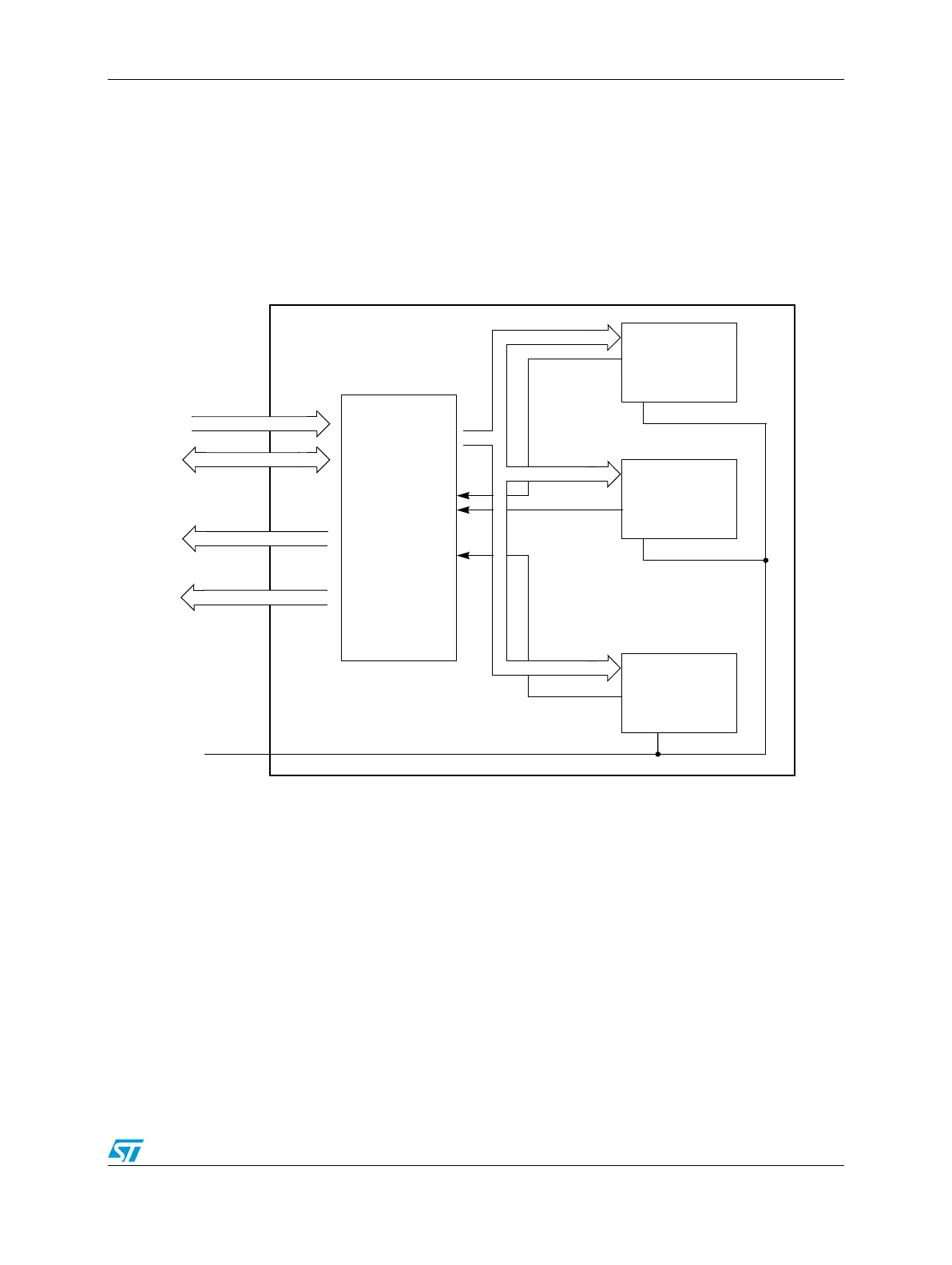
Figure 456 shows the PIT block diagram.
Figure 456. PIT block diagram
30.1.1 Overview
This chapter describes the function of the Periodic Interrupt Timer block (PIT). The PIT is an
array of four timers that can be used to raise interrupts and trigger DMA channels.
30.1.2 Features
The main features of this block are:
● Timers can generate DMA trigger pulses to initiate DMA transfers with other
peripherals (ex: initiate a SPI message transfer sequence)
● Timers can generate interrupts
● All interrupts are maskable
● Independent timeout periods for each timer
Timer 0
Timer 3
Timer 1
.
.
.
PIT
Registers
Peripheral
interrupts
timeout
load_value
PIT
.
.
.
triggers
bus
System clock