RM0046 FlexPWM
Doc ID 16912 Rev 5 689/936
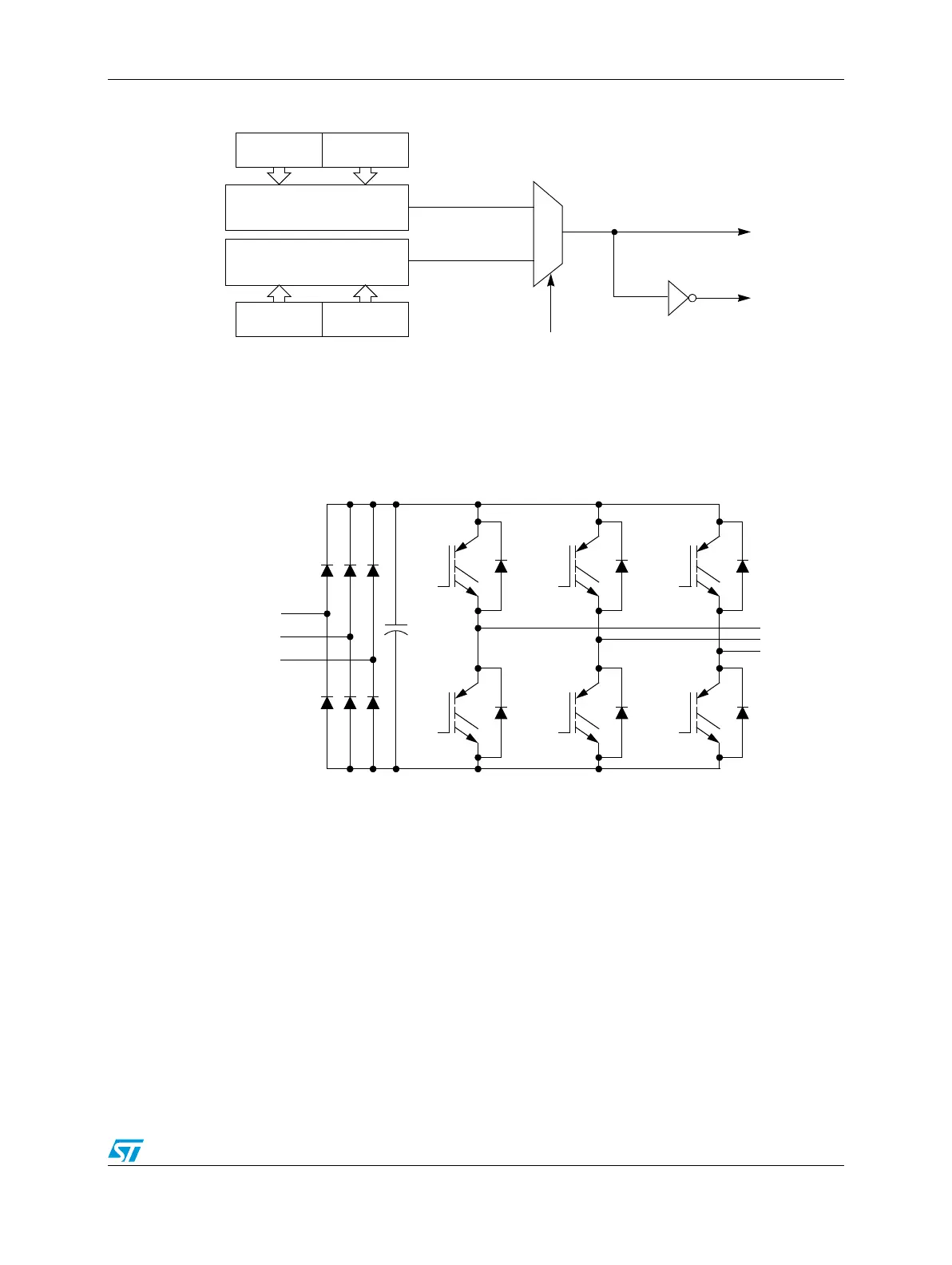
Figure 374. Complementary channel pair
The complementary channel operation is for driving top and bottom transistors in a motor
drive circuit, such as the one in Figure 375.
Figure 375. Typical 3-phase AC motor drive
Complementary operation allows the use of the deadtime insertion feature.
25.8.8 Deadtime insertion logic
Figure 376 shows the deadtime insertion logic of each submodule, which creates non-
overlapping complementary signals when not in independent mode.
VAL3VAL2
PWMA
PWMB
PWMA Generation
VAL5VAL4
PWMB Generation
0
1
IPOL
PWM
A0
PWM
A1
AC
INPUTS
TO
MOTOR
PWM
A2
PWM
B1
PWM
B2
PWM
B0