RM0046 LIN Controller (LINFlex)
Doc ID 16912 Rev 5 529/936
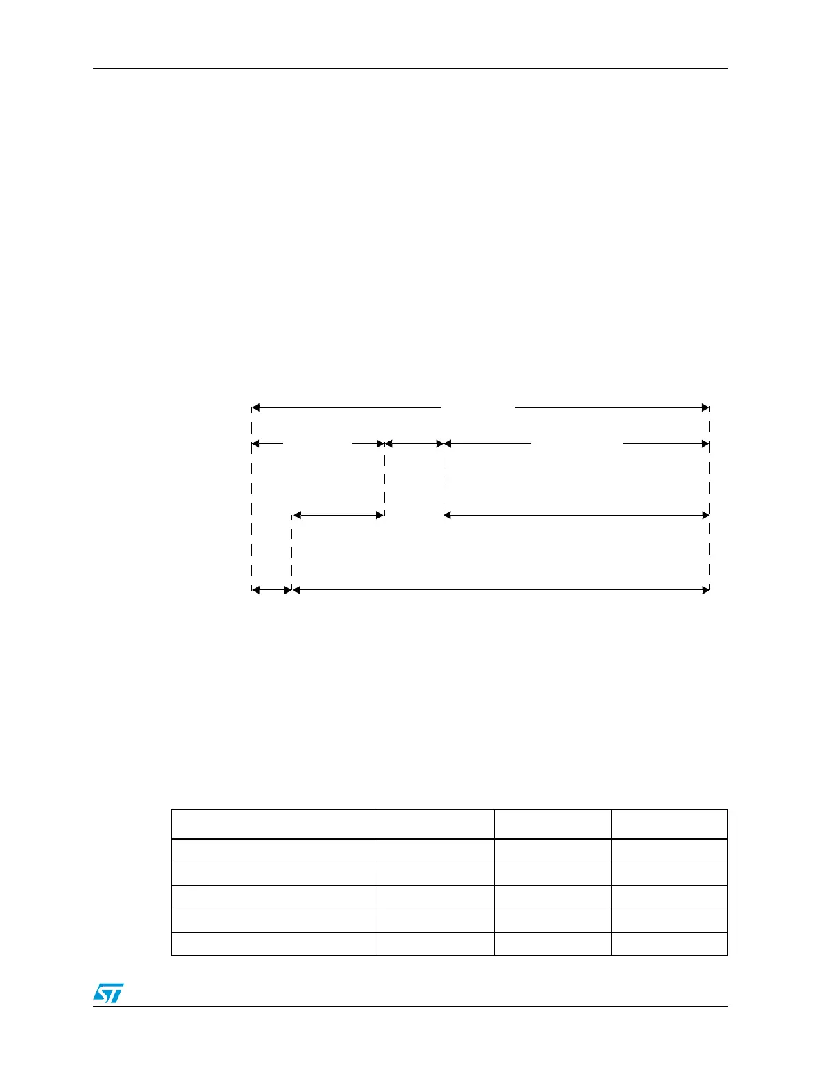
OC1 checks T
Header
and T
Response
and OC2 checks T
Frame
(see Figure 261).
When LINFlex moves from Break state to Break Delimiter state (see Section , LIN status
register (LINSR)):
● OC1 is updated with the value of OC
Header
(OC
Header
=CNT+HTO),
● OC2 is updated with the value of OC
Frame
(OC
Frame
=CNT+HTO +RTO×9 (frame
timeout value for an 8-byte frame)),
● The TOCE bit is set.
On the start bit of the first response data byte (and if no error occurred during the header
reception), OC1 is updated with the value of OC
Response
(OC
Response
= CNT + RTO × 9
(response timeout value for an 8-byte frame)).
Once the first response byte is received, OC1 and OC2 are automatically updated to check
T
Response
and T
Frame
according to RTO (tolerance) and DFL.
On the checksum reception or in case of error in the header or data field, the TOCE bit is
reset.
Figure 261. Header and response timeout
Output compare mode
Programming LINTCSR[LTOM] = 1 enables the output compare mode. This mode allows
the user to fully customize the use of the counter.
OC1 and OC2 output compare values can be updated in the LINTOCR by software.
21.8.4 Interrupts
OC
Frame
OC
Header
OC
Response
Header
Response
Break
Frame
OC1
OC2
Response
space
Table 262. LINFlex interrupt control
Interrupt event Event flag bit Enable control bit Interrupt vector
Header Received interrupt HRF HRIE RXI
(1)
Data Transmitted interrupt DTF DTIE TXI
Data Received interrupt DRF DRIE RXI
Data Buffer Empty interrupt DBEF DBEIE TXI
Data Buffer Full interrupt DBFF DBFIE RXI