Boot Assist Module (BAM) RM0046
820/936 Doc ID 16912 Rev 5
Configuration
SPC560P40/34 devices implement the autobaud feature via FlexCAN or LINFlex selecting
the active serial communication peripheral by means of an autoscan routine.
When autobaud configuration is selected by ABS and FAB pins, the autoscan routine starts
and listens to the active bus protocol. Initially the LinFlex_0 RX pin and FlexCAN_0 RX pin
are configured as GPIO inputs:
● for 100-pin LQFP package internal weak pull-up enabled for both RX pins
● for 64-pin LQFP package internal weak pull-up enabled only for FlexCAN_0 RX pin
The autoscan routine waits in polling for the first LOW level to select which routine will be
executed:
● FlexCAN Autobaud routine
● LinFlex Autobaud routine
Then the measurement baud rate is computed to configure the serial communication at the
right rate. In the end of baud rate measurement, LinFlex_0 RX pin and FlexCAN_0 RX pin
switches to work as dedicated pin.
Baud rate measurement is using the System Timer Module (STM) which is driven by the
system clock. Measurement itself is performed by software polling the related inputs as
general purpose IO’s, resulting in a detection granularity that is directly related to the
execution speed of the software.
One main difference of the autobaud feature is that the system clock is not driven directly by
the external oscillator, but it is driven by the FMPLL output. The reason is that to have an
optimum resolution for baud rate measurement, the system clock needs to be nearer to the
maximum allowed device’s frequency.
This is achieved with the following two steps:
1. using the Clock Monitor Unit (CMU) and the internal RC oscillator (IRC), the external
frequency is measured using the IRC as reference to determine this frequency.
2. Based on the result of this measurement, the FMPLL is programmed to generate a
system clock that is configured to be near, but lower, to the maximum allowed
frequency.
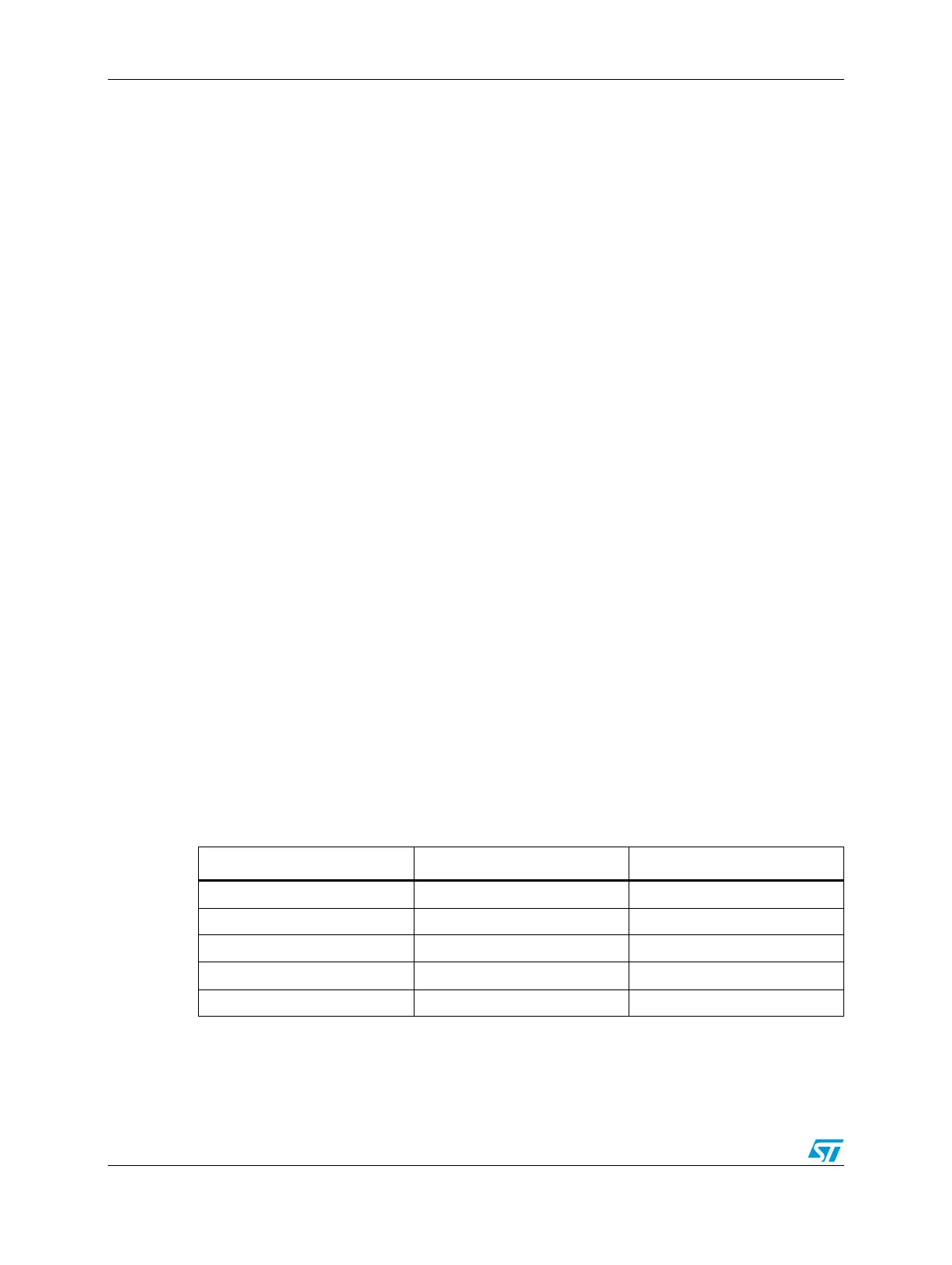
The relation between system clock frequency and external clock frequency with FMPLL
configuration value is shown in Table 4 4 3.
Table 443. System clock frequency related to external clock frequency
f
osc
[MHz] f
rc
/f
osc
(1)
1. These values and consequently the f
sys
suffer from the precision of RC internal oscillator used to measure
f
osc
through CMU module.
f
sys
[MHz]
4–8 4–2 16–32
8–12 2–4/3 32–48
12–16 4/3–1 36–48
16–24 1–2/3 32–48
> 24 < 2/3 > 24