RM0046 eTimer
Doc ID 16912 Rev 5 715/936
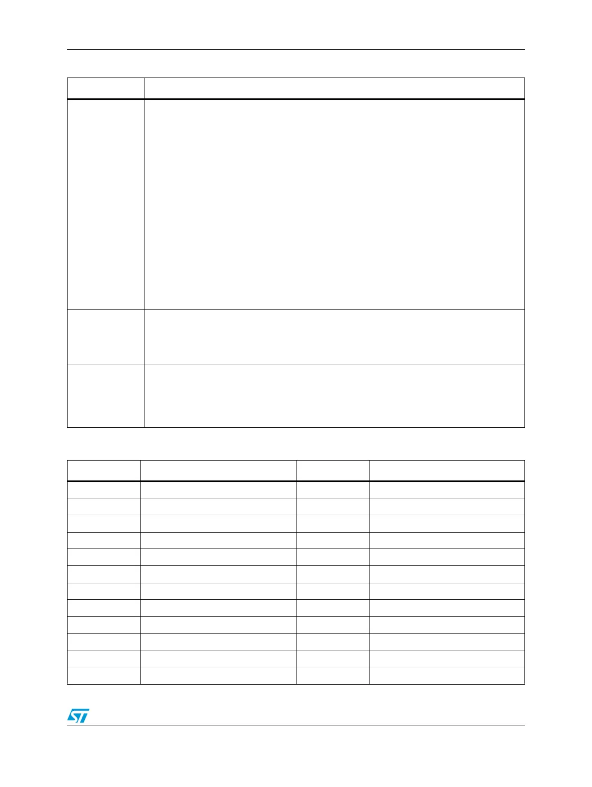
LENGTH
Count Length
This bit determines whether the counter counts to the compare value and then reinitializes itself
to the value specified in the LOAD, CMPLD1, or CMPLD2 registers, or the counter continues
counting past the compare value, to the binary roll over.
0 Continue counting to roll over.
1 Count until compare, then reinitialize.
The value that the counter is reinitialized with depends on the settings of CLC1 and CLC2. If
neither of these indicates the counter is to be loaded from one of the CMPLD registers, then the
LOAD register reinitializes the counter upon matching either COMP register. If one of CLC1 or
CLC2 indicates that the counter is to be loaded from one of the CMPLD registers, then the
counter will reinitialize to the value in the appropriate CMPLD register upon a match with the
appropriate COMP register. If both of the CLC1 and CLC2 fields indicate that the counter is to
be loaded from the CMPLD registers, then CMPLD1 will have priority if both compares happen
at the same value.
When output mode 0x4 is used, alternating values of COMP1 and COMP2 are used to
generate successful comparisons. For example, the counter counts until COMP1 value is
reached, reinitializes, then counts until COMP2 value is reached, reinitializes, then counts until
COMP1 value is reached, etc.
DIR
Count Direction
This bit selects either the normal count direction up, or the reverse direction, down.
0Count up.
1Count down.
SECSRC
Secondary Count Source
These bits identify the source to be used as a count command or timer command. The selected
input can trigger the timer to capture the current value of the CNTR register. The selected input
can also be used to specify the count direction. The polarity of the signal can be inverted by the
SIPS bit of the CTRL2 register.
Table 372. CTRL1 field descriptions (continued)
Field Description
Table 373. Count source values
Value Meaning Value Meaning
00000 Counter #0 input pin 10000 Counter #0 output
00001 Counter #1 input pin 10001 Counter #1 output
00010 Counter #2 input pin 10010 Counter #2 output
00011 Counter #3 input pin 10011 Counter #3 output
00100 Counter #4 input pin 10100 Counter #4 output
00101 Counter #5 input pin 10101 Counter #5 output
00110 Reserved 10110 Reserved
00111 Reserved 10111 Reserved
01000 Auxiliary input #0 pin 11000 IP Bus clock divide by 1 prescaler
01001 Auxiliary input #1 pin 11001 IP Bus clock divide by 2 prescaler
01010 Auxiliary input #2 pin 11010 IP Bus clock divide by 4 prescaler
01011 Reserved 11011 IP Bus clock divide by 8 prescaler