FlexPWM RM0046
684/936 Doc ID 16912 Rev 5
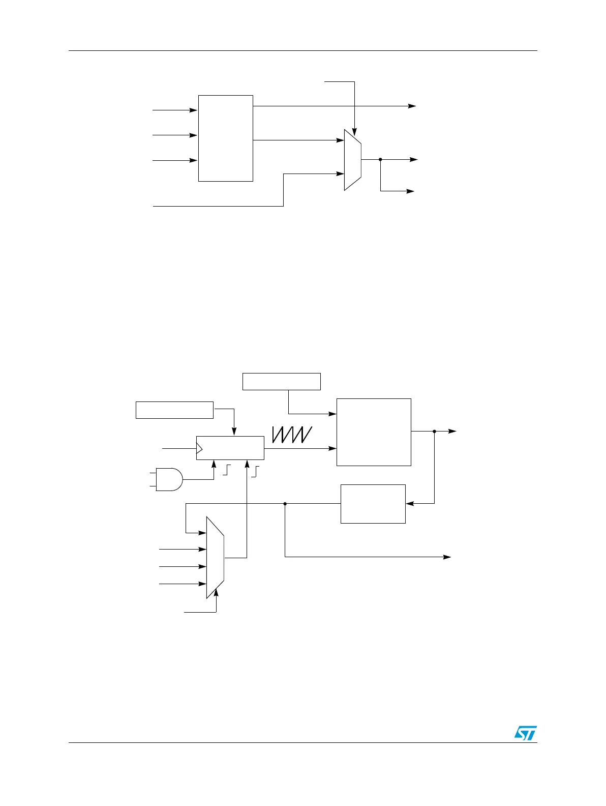
Figure 370. Register reload logic
25.8.3 Counter synchronization
Referring to Figure 371, the 16-bit counter will count up until its output equals VAL1, which
specifies the counter modulus value. The resulting compare causes a rising edge to occur
on the Local Sync signal, which is one of four possible sources used to cause the 16-bit
counter to be initialized with INIT. If Local Sync is selected as the counter initialization signal,
then VAL1 within the submodule effectively controls the timer period (and thus the PWM
frequency generated by that submodule) and everything works on a local level.
Figure 371. Submodule timer synchronization
The Master Sync signal originates as the Local Sync from submodule 0. If configured to do
so, the timer period of any submodule can be locked to the period of the timer in submodule
0. The VAL1 register and associated comparator of the other submodules can then be freed
up for other functions such as PWM generation, output compares, or output triggers.
0
1
Reload
Logic
(counts
PWM
cycles)
Local Reload
LDOK
Mod Compare
Half Compare
Master Reload
Register Reload
Master Reload
(from submod0 only)
RELOAD_SEL
Reload opportunity
(to on-chip trigger unit)
16-bit counter
INIT
Init
16-bit
comparator
VAL1
Mod Compare
Processing
Logic
Master Reload
EXT_SYNC
Master Sync
0
1
2
3
INIT_SEL
Local Sync
Master Sync
(from submod0
only)
Submodule Clock
FORCE_OUT
FORCE_EN