RM0046 Deserial Serial Peripheral Interface (DSPI)
Doc ID 16912 Rev 5 441/936
20.6.2 Signal names and descriptions
Peripheral Chip Select / Slave Select (CS_0)
In master mode, the CS_0 signal is a peripheral chip select output that selects the slave
device to which the current transmission is intended.
In slave mode, the CS_0 signal is a slave select input signal that allows an SPI master to
select the DSPI as the target for transmission. CS_0 must be configured as input and pulled
high. If the internal pullup is being used then the appropriate bits in the relevant SIU_PCR
must be set (SIU_PCR [WPE = 1], [WPS = 1]).
Set the IBE and OBE bits in the PCR register for all CS_0 pins when the DSPI chip select or
slave select primary function is selected for that pin. When the pin is used for DSPI master
mode as a chip select output, set the OBE bit. When the pin is used in DSPI slave mode as
a slave select input, set the IBE bit.
Refer to Section , “Pad Configuration Registers (PCR[0:71]) for more information.
Peripheral Chip Selects 1–3 (CS1:3)
CS1:3 are peripheral chip select output signals in master mode. In slave mode these signals
are not used. On DSPI_0, these are CS1:3
and CS5:6.
Peripheral Chip Select 4 (CS4)
CS4 is a peripheral chip select output signal in master mode.
Peripheral Chip Select 5/Peripheral Chip Select Strobe (CS_5)
CS5 is a peripheral chip select output signal. When the DSPI is in master mode and PCSSE
bit in the DSPIx_MCR is cleared, the CS5
signal selects the slave device that receives the
current transfer.
CS5
is a strobe signal used by external logic for deglitching of the CS signals. When the
DSPI is in master mode and the PCSSE bit in the DSPIx_MCR is set, the CS5
signal
indicates the timing to decode CS0:4
signals, which prevents glitches from occurring.
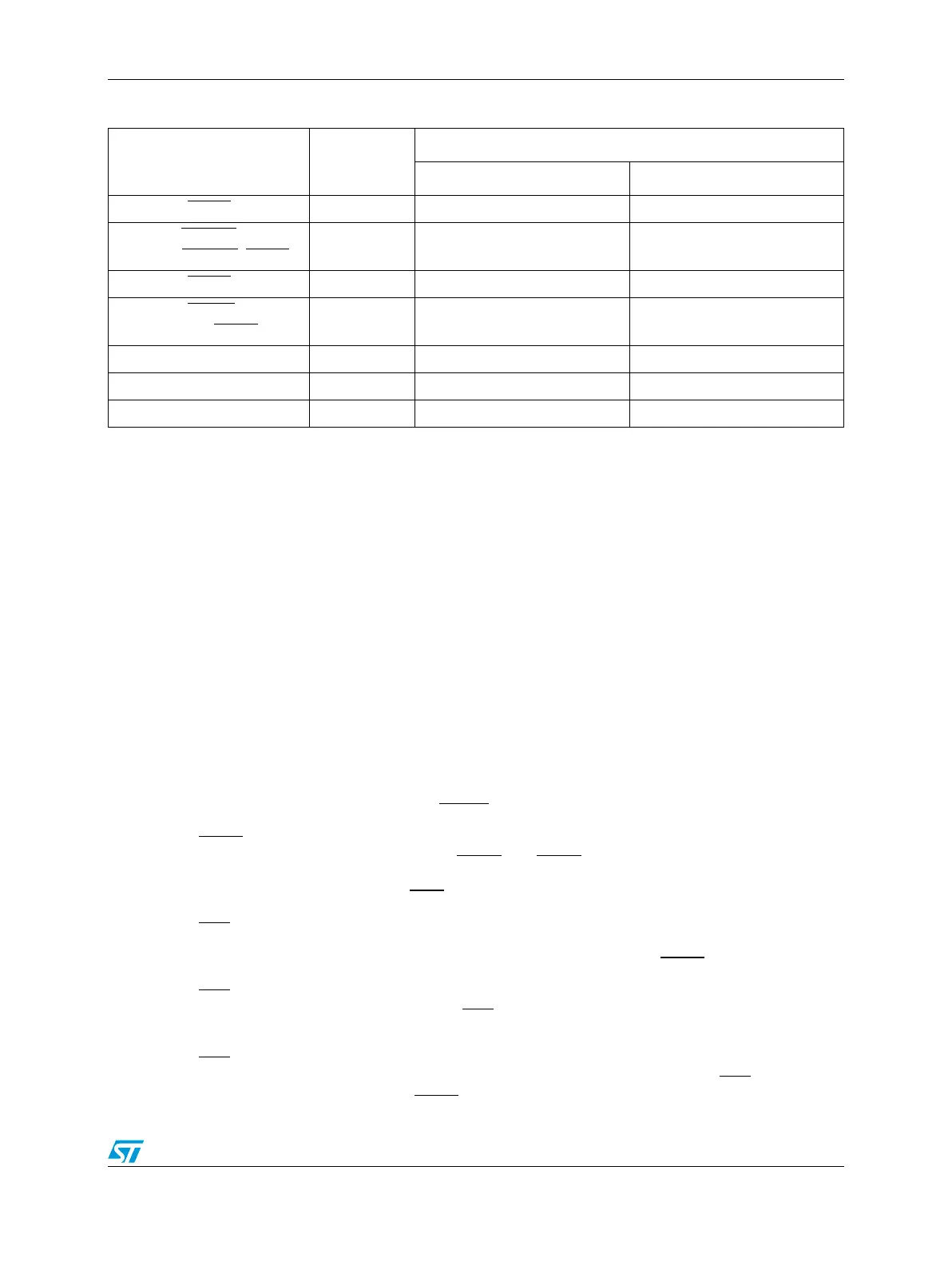
Table 204. Signal properties
Name I/O type
Function
Master mode Slave mode
CS0_
x Output / input Peripheral chip select 0 Slave select
CS1:3_
x
(DSPI 0: CS1:3_0, CS5_0)
Output Peripheral chip select 1–3 Unused
(1)
CS4_x Output Peripheral chip select 4 Master trigger
CS5_
x
(DSPI 0: CS7_0)
Output
Peripheral chip select 5 /
Peripheral chip select strobe
Unused
(1)
SIN_x Input Serial data in Serial data in
SOUT_x Output Serial data out Serial data out
SCK_x Output / input Serial clock (output) Serial clock (input)
1. The SIUL allows you to select alternate pin functions for the device.