FlexPWM RM0046
698/936 Doc ID 16912 Rev 5
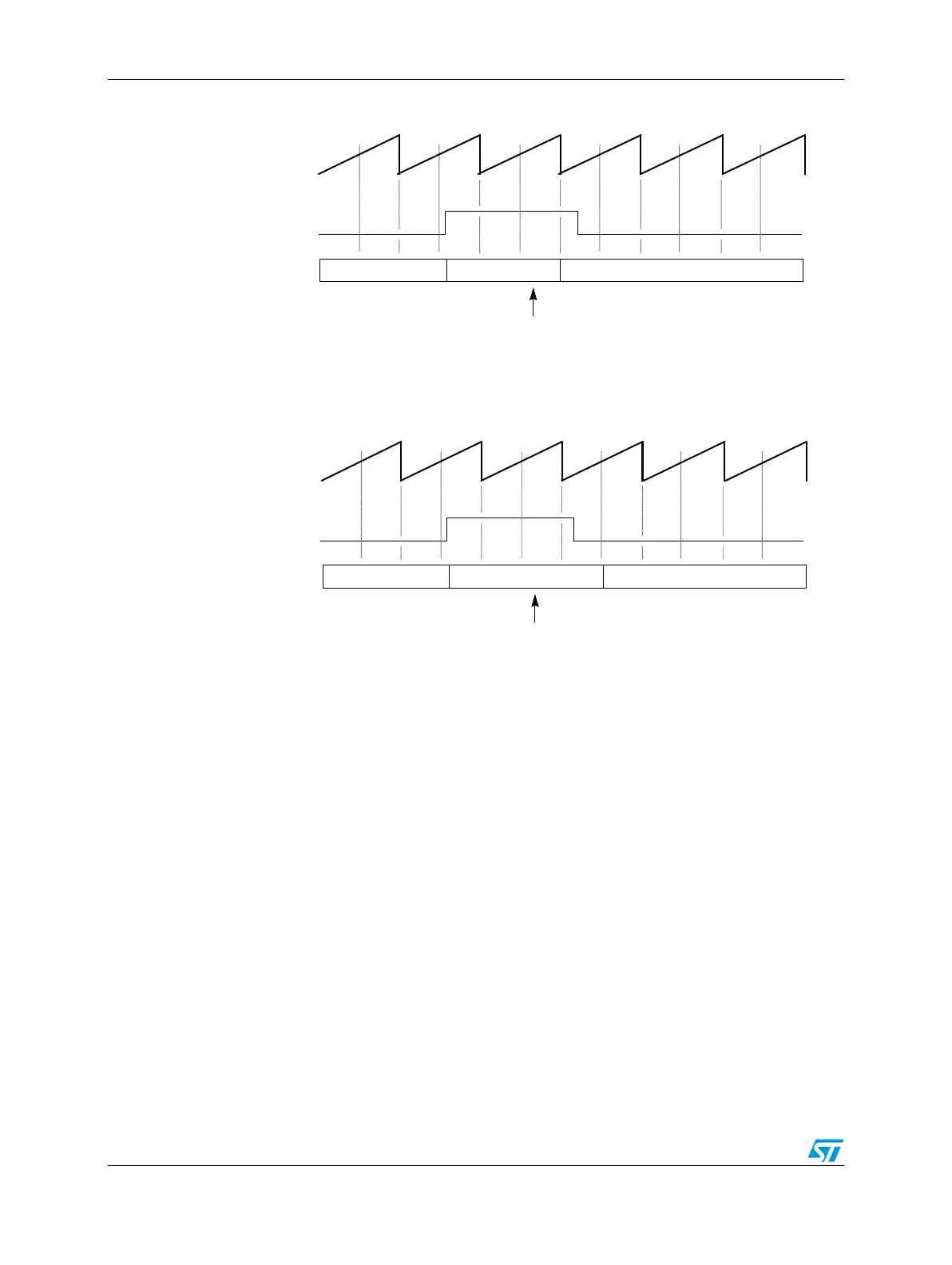
Figure 384. Manual fault clearing (FSAFE = 0)
Figure 385. Manual fault clearing (FSAFE = 1)
Note: Fault protection also applies during software output control when the SELA and SELB fields
are set to select OUTA and OUTB bits. Fault clearing still occurs at half PWM cycle
boundaries while the PWM generator is engaged, RUN equals one. But the OUTx bits can
control the PWM pins while the PWM generator is off, RUN equals zero. Thus, fault clearing
occurs at IPBus cycles while the PWM generator is off and at the start of PWM cycles when
the generator is engaged.
25.8.16 Fault testing
The FTEST bit simulates a fault condition on each of the fault inputs.
25.9 PWM generator loading
25.9.1 Load enable
The LDOK bit enables loading of the following PWM generator parameters:
● The prescaler divisor—from the PRSC bits in the CTRL1 register
● The PWM period and pulse width—from the INIT and VALx registers
ENABLED
FFPINx BIT
ENABLED DISABLED
FFLAGx
CLEARED
COUNT
OUTPUTS
ENABLED
FFPINx BIT
ENABLED DISABLED
FFLAGx
CLEARED
COUNT
OUTPUTS