RM0046 Clock Description
Doc ID 16912 Rev 5 99/936
Main features are:
● Oscillator clock available interrupt
● Oscillator bypass mode
4.7.1 Functional description
The crystal oscillator circuit includes an internal oscillator driver and an external crystal
circuitry. The XOSC provides an output clock to the PLL or it is used as a reference clock to
specific modules depending on system needs.
The crystal oscillator can be controlled by the ME:
● Control by ME module. The OSCON bit of the ME_xxx_MCRs controls the powerdown
of oscillator based on the current device mode while S_OSC of ME_GS register
provides the oscillator clock available status.
After system reset, the oscillator is put to power down state and software has to switch on
when required. Whenever the crystal oscillator is switched on from off state, OSCCNT
counter starts and when it reaches the value EOCV[7:0] × 512, oscillator clock is made
available to the system. Also an interrupt pending bit I_OSC of OSC_CTL register is set. An
interrupt will be generated if the interrupt mask bit M_OSC is set.
The oscillator circuit can be bypassed by setting OSC_CTL[OSCBYP]. This bit can only be
set by the software. System reset is needed to reset this bit. In this bypass mode, the output
clock has the same polarity as external clock applied on EXTAL pin and the oscillator status
is forced to ‘1’. The bypass configuration is independent of the powerdown mode of the
oscillator.
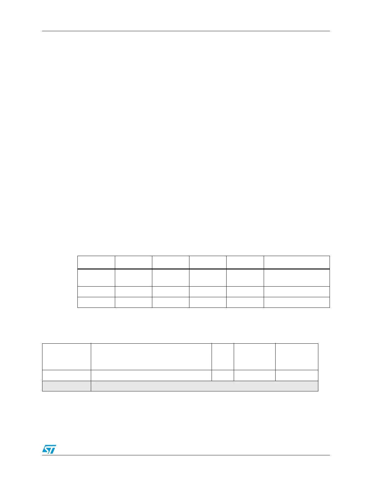
Table 9 shows the truth table of different configurations of oscillator.
4.7.2 Register description
Table 9. Crystal oscillator truth table
ENABLE BYP XTALIN EXTAL CK_OSCM XOSC Mode
00
No crystal,
High Z
No crystal,
High Z
0 Power down, IDDQ
x 1 x Ext clock EXTAL Bypass, XOSC disabled
1 0 Crystal Crystal EXTAL Normal, XOSC enabled
Table 10. OSC_CTL memory map
Offset from
OSC_CTL_BASE
(0xC3FE_0000)
Register
Access
Reset value Location
0x0000 OSC_CTL—Oscillator control register R/W 0x0080_0000 on page 4-99
0x0004–0x000F Reserved